

Choosing a centrifugal compressor vs reciprocating model is a high-stakes decision for chemical plants where selecting the wrong machinery can trigger millions of dollars in unexpected energy costs and process downtime. Chemical manufacturing environments present highly demanding operational challenges, requiring process engineers to meticulously weigh continuous large-scale volumetric capacity against precise, extreme-pressure gas delivery.
What is the Primary Difference in a Centrifugal Compressor vs Reciprocatin Process?
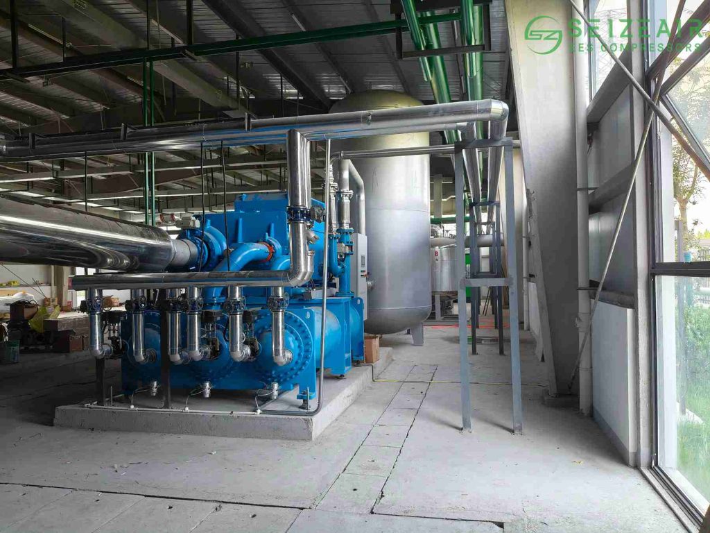
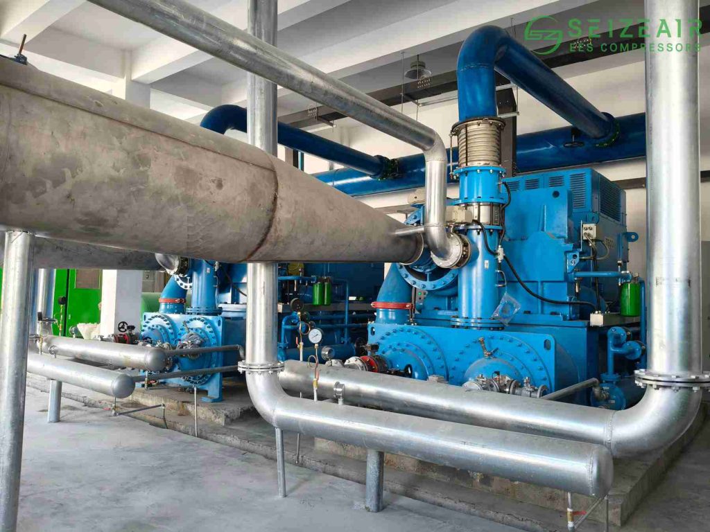
Understanding the core physics separating these two systems requires looking at how they transfer energy to a gas stream. A centrifugal compressor is a dynamic machine that relies on kinetic energy conversion. Gas enters the center of a rapidly spinning impeller horizontally, and centrifugal force flings the gas outward radially. As the gas accelerates to extreme velocities, it passes into a stationary diffuser section where the kinetic energy converts directly into static pressure. Because this gas path remains completely open during operation, the flow profile is continuous, steady, and free of the pressure pulsations that shake downstream piping networks.
Conversely, a reciprocating compressor works on the principle of positive displacement, using a mechanical design that functions like an internal combustion engine in reverse. A crankshaft drives a piston back and forth inside a tightly sealed cylinder. When the piston moves backward, it creates a vacuum that draws a specific volume of gas through a suction valve. As the piston drives forward, it physically traps the gas and shrinks the chamber volume, compressing the molecules together until the internal force overcomes the spring-loaded discharge valve. This action creates a highly pressurized but distinctly pulsating gas stream that requires heavy pulsation dampening vessels downstream to protect delicate instruments.
Centrifugal Compressor vs Reciprocating
| Operating Parameter | Centrifugal Compressor | Reciprocating Compressor |
| Flow Rate Capability | High to extreme (up to 300,000 cfm) | Low to moderate (typically under 10,000 cfm) |
| Discharge Pressure | Moderate to high (up to 800 psi normally) | Extremely high (up to 10,000+ psi) |
| Flow Characteristics | Continuous, pulse-free stream | Intermittent, heavily pulsating stream |
| Footprint & Weight | Compact relative to its high capacity | Large, heavy, requires massive concrete foundations |
| Turn-down Performance | Limited by surge limits (typically 70% to 100%) | Excellent (0% to 100% via clearance pockets/stepless valves) |
| Turndown Efficiency | Drops significantly near surge point | Remains highly efficient across the curve |
| Maintenance Interval | Long run times (up to 3 to 5 years without shutdown) | Frequent (valves/rings need service every 6 to 12 months) |
When to Choose a Centrifugal Compressor for Chemical Processes?
Centrifugal machinery excels in massive, centralized chemical manufacturing setups designed for continuous, round-the-clock base-load production. If your facility runs large-scale ethylene cracking plants, ammonia synthesis loops, or major air separation units (ASUs), you need a massive, steady flow of process gas to feed downstream catalytic reactors without interruption. In these scenarios, the sheer volumetric capability of a dynamic machine makes it the only practical choice, easily moving hundreds of thousands of cubic feet of gas per minute.
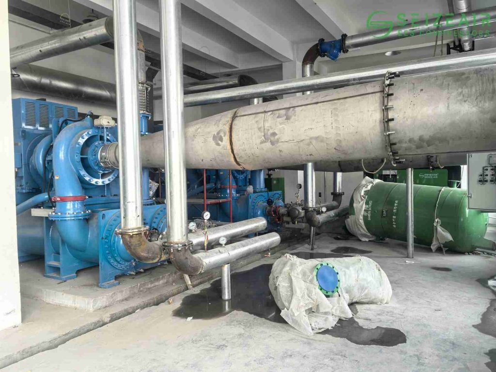
Maintenance intervals are another crucial factor for plant managers trying to hit strict yearly uptime metrics. Because the impellers inside a dynamic machine spin freely without rubbing or touching the internal casings, there are very few contacting components that experience mechanical wear. The entire system relies on high-performance hydrodynamic bearings and dry gas seals to isolate the process loop. As a result, leading chemical complexes routinely operate these machines continuously for three to five years without a single maintenance stoppage. If your goal is to minimize routine mechanical interventions, reviewing advanced aerodynamic solutions from premium manufacturers like Seize Air ensures your long-term plant availability metrics remain fully secured.
Beyond mechanical wear, process purity often dictates your machine choice. Many modern chemical synthesis loops utilize expensive platinum or palladium catalysts that are easily ruined by microscopic traces of oil contamination. Because the lubrication systems in centrifugal units are located completely outside the gas compression path behind sophisticated labyrinth seals, the process stream remains entirely oil-free. This eliminates the need for complex downstream filtration arrays that cause pressure drops and demand regular filter element replacements.
When Should Engineers Select a Reciprocating Compressor over Centrifugal?
Despite the high-volume advantages of dynamic units, positive displacement piston compressors are essential in specific, high-intensity processing loops. When your process demands extreme pressures—such as in high-pressure hydrogen recycling, low-density polyethylene (LDPE) reactors, or gas bottling facilities—dynamic impellers fall short. Because light gases lack the density required to generate high pressure differentials through velocity alone, a centrifugal unit would require an impractical number of compression stages. A reciprocating piston physically forces the gas into a confined space, easily achieving discharge pressures exceeding 5,000 to 10,000 psi in multi-stage configurations.
Flexibility under changing plant conditions is another area where reciprocating units excel. Chemical plants frequently adjust their production outputs based on seasonal market demand or feed stock availability. Reciprocating compressors manage variable flow profiles exceptionally well, maintaining excellent thermodynamic efficiency even when turned down to 20% or 0% capacity by using clearance pockets, finger unloaders, or stepless variable-induction valves.
Furthermore, if your process handles variable gas compositions—such as refinery off-gases where the molecular weight shifts wildly from batch to batch—a reciprocating machine keeps pumping reliably. It simply displaces the volume trapped in the cylinder regardless of gas density. A centrifugal machine, by contrast, could instantly experience a dangerous surge condition or choke limit if the molecular weight drops below the aerodynamic design point.
Which System Offers Better Efficiency for Dynamic Chemical Plant Loads?
Evaluating the efficiency of a centrifugal compressor vs reciprocating machine requires looking closely at your plant’s specific operational profile rather than just comparing peak design numbers. At 100% rated capacity on a steady base-load application, a custom-engineered centrifugal machine operates with outstanding polytropic efficiency. However, if your chemical process experiences regular demand swings, the efficiency curve shifts dramatically. When a centrifugal compressor is forced to operate below its minimum turndown limit (typically around 70% to 75% of design flow), it faces a phenomenon known as aerodynamic surge—a dangerous reversal of gas flow. To prevent this, the control system must open an anti-surge valve, recycling a portion of the compressed gas back to the inlet. This means you are paying to compress the exact same gas multiple times, heavily damaging your overall energy efficiency.
Reciprocating compressors hold a clear edge in efficiency across variable operating ranges. Because they rely on positive displacement, their volumetric and adiabatic efficiency remains high even when flow rates drop significantly. The power consumed by a piston unit scales down almost linearly with flow reductions, ensuring that you only pay for the exact volume of gas your downstream process requires. For facilities running multi-product batch processes with fluctuating daily flows, a reciprocating layout uses less total kilowatt-hours over a calendar year. However, before finalizing your equipment configurations, consulting with specialized application engineers like Seize Air can help you model precise lifecycle cost assessments to determine exactly which technology will yield the lowest lifetime operating expenses.
Maintenance and Operational Cost Analysis
The initial purchase price of a industrial compressor represents less than 20% of its total lifetime cost of ownership (TCO), with power consumption and routine maintenance dominating plant budgets over a standard 20-year service life.
The Maintenance Reality of Reciprocating Piston Designs
Pistons rely on rider bands, compression rings, and suction or discharge valves that mechanically open and slam shut up to 1,000 times per minute. These components are subjected to intense mechanical stress, friction, and thermal loading. As a result, plant operators must schedule short maintenance windows every 6 to 12 months to replace worn valves and inspect piston rod packing seals. If these routine service windows are ignored, a worn valve can leak hot gas back into the cylinder, leading to overheating, accelerated ring wear, and eventually a catastrophic rod drop that can destroy the cylinder lining.
The Maintenance Reality of Centrifugal Rotor Assemblies
Centrifugal compressors require very few routine interventions because they do not contain high-wear reciprocating components. However, when a dynamic machine does suffer a component failure, the repair costs and lead times are significantly higher. If a foreign object bypasses the inlet filtration system, or if a severe process upset triggers prolonged aerodynamic surging, the resulting vibration can ruin the high-speed rotor balance. Because these impellers spin at velocities ranging from 10,000 to over 30,000 RPM, even a minor micro-gram imbalance can wipe out the hydrodynamic bearings and damage the dry gas seals. Repairing this type of failure requires specialized field technicians, precision balancing equipment, and weeks of costly plant downtime.
Capital Cost vs Total Cost of Ownership (TCO)
| Expense Component | Centrifugal System | Reciprocating System |
| Initial Purchase Price (CapEx) | Higher for low flows; Lower per cfm at high flows | Lower for low capacities; High for large multi-stage units |
| Foundation/Installation Cost | Minimal; basic balanced skid needed | Massive; requires deep concrete foundations to damp vibrations |
| Routine Maintenance Parts | Low frequency, high individual cost | High frequency, lower individual component cost |
| Power Consumption Costs | Highly optimized for steady 24/7 base loads | Highly optimized for fluctuating, high-pressure loops |
Key Selection Factors Checklist for Chemical Plant Engineers
To select the most reliable machine for your gas processing project, evaluate your workflow parameters against this engineering criteria list:
- Gas Molecular Weight: Light gases like pure hydrogen are difficult to compress efficiently using centrifugal impellers without adding an impractical number of stages. Reciprocating cylinders handle low molecular weights easily because they do not rely on gas velocity to create pressure.
- Flow Stability Profile: If your downstream chemical reactors operate on a variable or batch schedule where flow demands routinely fall below 70% of design capacity, standard centrifugal options will waste energy via gas recycling. A reciprocating option handles these swings easily.
- Foundation and Structural Constraints: Reciprocating machinery generates significant low-frequency structural vibrations due to the inertia of the heavy moving pistons. They require deep, heavily reinforced concrete foundations. Centrifugal units operate smoothly with almost zero low-frequency vibration, making them suitable for elevated structures or space-constrained skids.
- Process Fluid Purity Requirements: If your process catalysts are highly sensitive to trace hydrocarbons, choosing a dedicated oil-free centrifugal setup or a completely non-lubricated reciprocating unit with Teflon-filled rings is mandatory to protect your chemical yields.
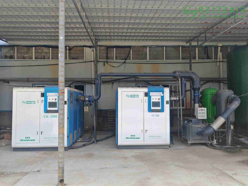
If you are currently evaluating your facility’s long-term utility needs and require high-reliability air or gas systems, partnering with an experienced industry specialist like Seize Air provides access to field-proven equipment engineered to withstand the most demanding chemical environments.
Connect with Our Compression Specialists
Choosing the right compression system for a chemical plant requires deep technical insight and careful planning. Making the wrong choice can cause years of frequent maintenance shutdowns, high energy bills, and costly production bottlenecks.
Don’t leave your process reliability to chance. Contact the engineering team at Seize Air today to get a comprehensive review of your gas composition, flow sheets, and pressure requirements. We will design a dependable, high-efficiency system that keeps your plant running smoothly for decades.