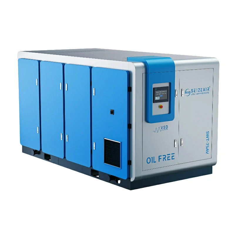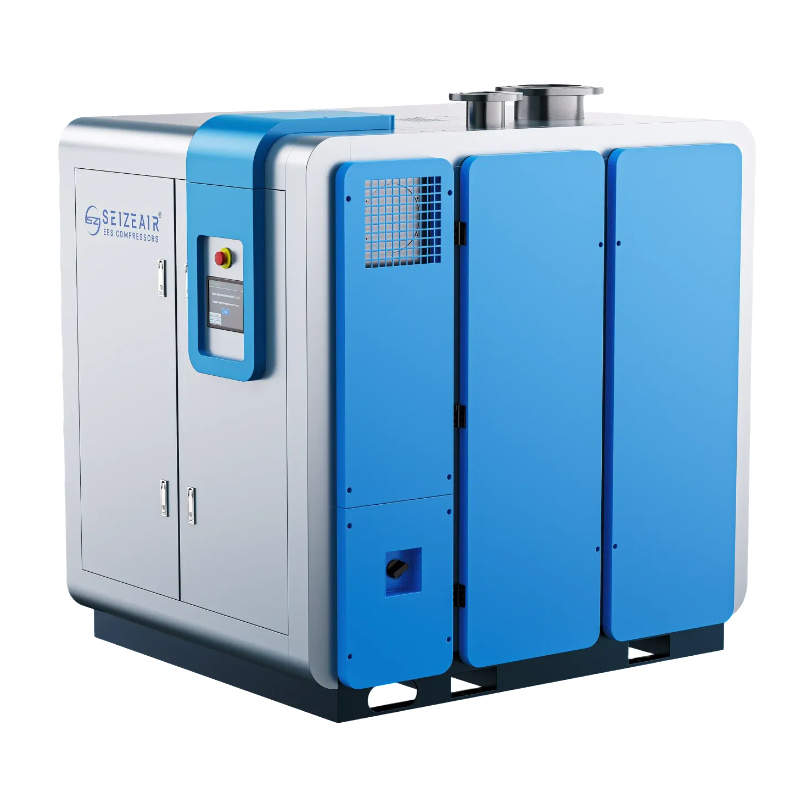


Centrifugal compressors handle high-volume, continuous gas transport across oil and gas operations where pressure demands in upstream extraction, midstream transport, and downstream refining require precise aerodynamic staging, impeller selection, and sealing configurations.
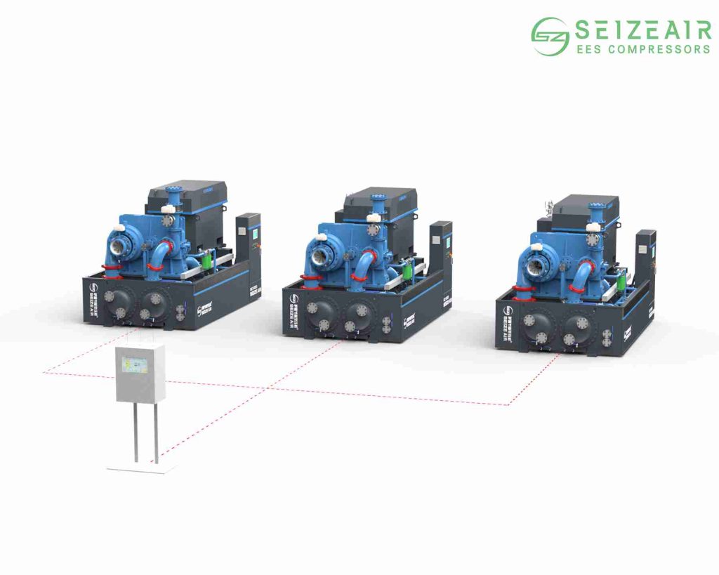
What Is a Centrifugal Compressor and How Does It Work in Oil and Gas?
A centrifugal compressor—a key type of dynamic, continuous-flow turbomachinery—uses high-speed rotating impellers to impart kinetic energy to process gas. As the gas flows radially outward through the impeller blades, its velocity increases rapidly. It then enters a diffuser section, where the flow channel expands, converting high kinetic energy into static pressure according to Bernoulli’s principle.
Unlike positive displacement machines (such as reciprocating or rotary screw units), dynamic centrifugal units depend on continuous, high-volume flow momentum rather than physically trapping fixed gas volumes.
Key Aerodynamic Performance Formulas
- Polytropic Head Equation:Hp = (Z_avg * R * T1 / ((n – 1) / n)) * [ (P2 / P1) ^ ((n – 1) / n) – 1 ]
- Pressure Ratio: Rc = P2 / P1
- Gas Power Output Requirements:Power = (Mass Flow Rate * Hp) / Polytropic Efficiency
In hydrocarbon processing, gas compositions range from clean methane to heavy streams rich in hydrogen sulfide (H2S), carbon dioxide (CO2), and heavy natural gas liquids (NGLs). Selecting an optimal centrifugal compressor requires matching impeller geometry, seal gas selection, and metallurgy precisely to the gas molecular weight (MW) and operating envelope.
What Are the Primary Applications of Centrifugal Compressors in Upstream Operations?
Upstream oil and gas extraction requires boosting gas pressures at the wellhead or offshore topsides. Upstream field gas pressures fluctuate constantly, requiring highly flexible aerodynamic staging and variable speed control.
1. Offshore Platform Gas Lift Operations
Gas lift introduces high-pressure gas into the wellbore to lighten the fluid column, restoring hydrocarbon flow in depleted reservoirs.
- High Pressure Ratios: Requires multi-stage centrifugal compressor configurations capable of boosting low-pressure casing gas (10 to 30 bar) to high injection pressures (150 to 350+ bar).
- Footprint & Weight Constraints: Offshore topsides demand maximum power density per square meter. Centrifugal turbomachinery delivers massive volumetric throughput within a compact footprint compared to heavy reciprocating engine packages.
- Variable Gas Composition: Handles shifting gas-to-oil ratios (GOR) without severe mechanical shock or sudden rod-load limits.
2. Associated Petroleum Gas (APG) Compression & Flare Recovery
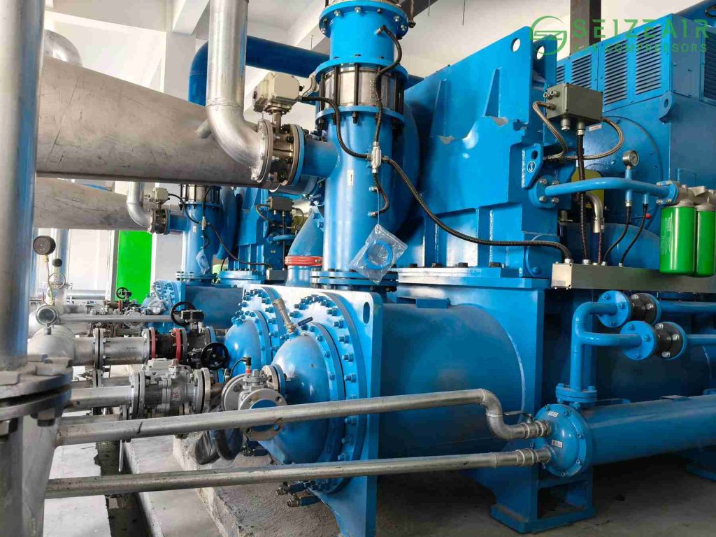
Instead of flaring valuable gas at wellheads, producers capture, compress, and process APG to generate revenue while adhering to zero-flare mandates. Multi-stage centrifugal compressors manage flow swings while avoiding liquid slugging damage through upstream scrubbers and knockout drums.
| Upstream Application | Typical Suction Pressure (bar) | Typical Discharge Pressure (bar) | Key Engineering Challenge | Preferred Design Standard |
| Offshore Gas Lift | 10 – 30 | 150 – 350 | Space/weight constraints, severe vibration isolation | API 617 barrel casing (Type 2in1) |
| APG Flare Recovery | 0.5 – 2 | 20 – 50 | Heavy hydrocarbon condensation, corrosive wet H2S | API 617 horizontally split / API 672 |
| Subsea Compression | 20 – 50 | 80 – 150 | Hermetically sealed motor, remote reliability | Direct-drive high-speed motor, canned rotor |
How Are Centrifugal Compressors Used in Midstream Gas Transportation and Storage?
Midstream networks move natural gas across continents and manage inventory inside underground storage facilities.
Mainline Gas Pipeline Compressor Stations
Pipeline transport requires moving billions of standard cubic feet of natural gas daily over thousands of miles. Frictional head loss drops line pressure over distance, requiring booster compressor stations every 40 to 100 miles.
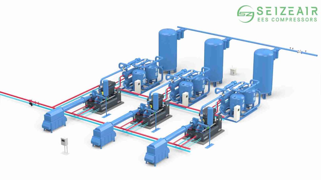
Single-stage centrifugal pipeline boosters or two-stage overhung units are directly driven by industrial gas turbines or variable-frequency drive (VFD) electric motors. Polytropic efficiency exceeding 85% directly lowers fuel gas consumption along transmission routes.
Underground Gas Storage (UGS) Injection and Withdrawal
Storage facilities (depleted reservoirs, aquifers, and salt caverns) buffer seasonal heating and cooling demand spikes:
- Injection Mode (Summer): High pressure ratio, variable flow rate to push gas deep underground against rising reservoir backpressure.
- Withdrawal Mode (Winter): Low pressure boost to deliver stored gas back into high-pressure transmission networks at high flow rates.
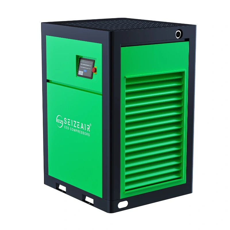
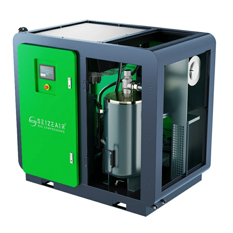
Operators rely on variable inlet guide vanes (IGVs) and VFD drives to adjust operating points across wide turndown ranges without driving units into surge. When outfitting plant utilities or field air-driven control systems around pipeline hubs, primary gas boosters operate alongside heavy-duty station utility air systems from trusted providers like Seize Air to ensure uninterrupted control valve actuation and reliable pneumatic tooling.
Why Are Centrifugal Compressors Essential in Downstream Refining and Petrochemicals?
Downstream processing turns crude oil and natural gas liquids into fuels, polymers, and specialty chemicals. Continuous run-times (3 to 6 years between turnarounds) make centrifugal turbomachinery the industry benchmark.
1. Fluid Catalytic Cracking (FCC) Wet Gas Compressors
FCC units break heavy hydrocarbon molecules into lighter gasoline and distillate fractions. The resulting wet gas stream contains light hydrocarbons, hydrogen, and trace particulate contaminants.
- Centrifugal wet gas compressors handle large volumes of low-density gas while resisting fouling from fine catalyst particles and polymerization products.
- Interstage cooling and wash-water injection systems prevent heavy end condensation and fouling inside internal diffuser passages.
2. Hydroprocessing Hydrogen Recycle Compressors
Hydrotreating and hydrocracking remove sulfur and nitrogen contaminants while breaking down heavy feeds under high hydrogen partial pressures.
- Pure hydrogen features an extremely low molecular weight (MW ~ 2.016).
- Low gas density demands high impeller tip speeds (exceeding 450 m/s) and multiple stages (8 to 10 impellers across dual casings) to build up necessary head.
3. Ethylene and Propylene Refrigeration Loops
Ethylene plants use multi-service, split-casing centrifugal units inside complex closed-loop refrigeration cycles (C2, C3 refrigerants) operating down to -100 degrees C. Side-stream inlets allow gas to enter the compressor casing at intermediate pressure levels, optimizing thermodynamic loop performance.
How Does a Centrifugal Compressor Compare to Reciprocating and Rotary Screw Types?
Choosing between dynamic (centrifugal) and positive displacement (reciprocating or rotary screw) machines depends on flow volume, discharge pressure, gas molecular weight variability, and lifecycle maintenance cost.
| Feature / Metric | Centrifugal Compressor | Reciprocating Compressor | Industrial Rotary Screw Compressor |
| Operating Principle | Dynamic (Kinetic to Pressure) | Positive Displacement (Piston) | Positive Displacement (Rotary Meshing) |
| Volumetric Flow Capacity | Very High (up to 500,000+ m3/h) | Low to Medium (below 15,000 m3/h) | Medium (up to 40,000 m3/h) |
| Discharge Pressure Limit | High (up to 1,000 bar in barrel casing) | Extremely High (up to 3,000+ bar) | Moderate (up to 40 bar) |
| Footprint per Flow Ratio | Very Small / Compact | Large & Heavy Foundation Required | Compact / Modular Skid |
| Gas MW Sensitivity | High (Head varies with MW) | None (Displacement fixed by volume) | Low |
| Maintenance Interval | Long (3 to 6 years continuous) | Short (frequent valves/rings service) | Medium (bearing and rotor service) |
| Flow Modulation Method | VFD, IGVs, Speed Control, Bypass | Speed control, clearance pockets | Slide valve, VFD contro |
Rule of Thumb: If process demands exceed 15,000 m3/h continuous flow with high availability needs, centrifugal units are the most cost-effective choice. For low-flow, ultra-high-pressure applications with fluctuating gas compositions, reciprocating machines remain relevant.
What Key Technologies Drive Modern Centrifugal Compressor Efficiency and Reliability?
Modern centrifugal compressors rely on advanced sub-components to ensure zero process gas leakage and high availability in harsh operating environments.
1. Advanced Impeller Aerodynamics
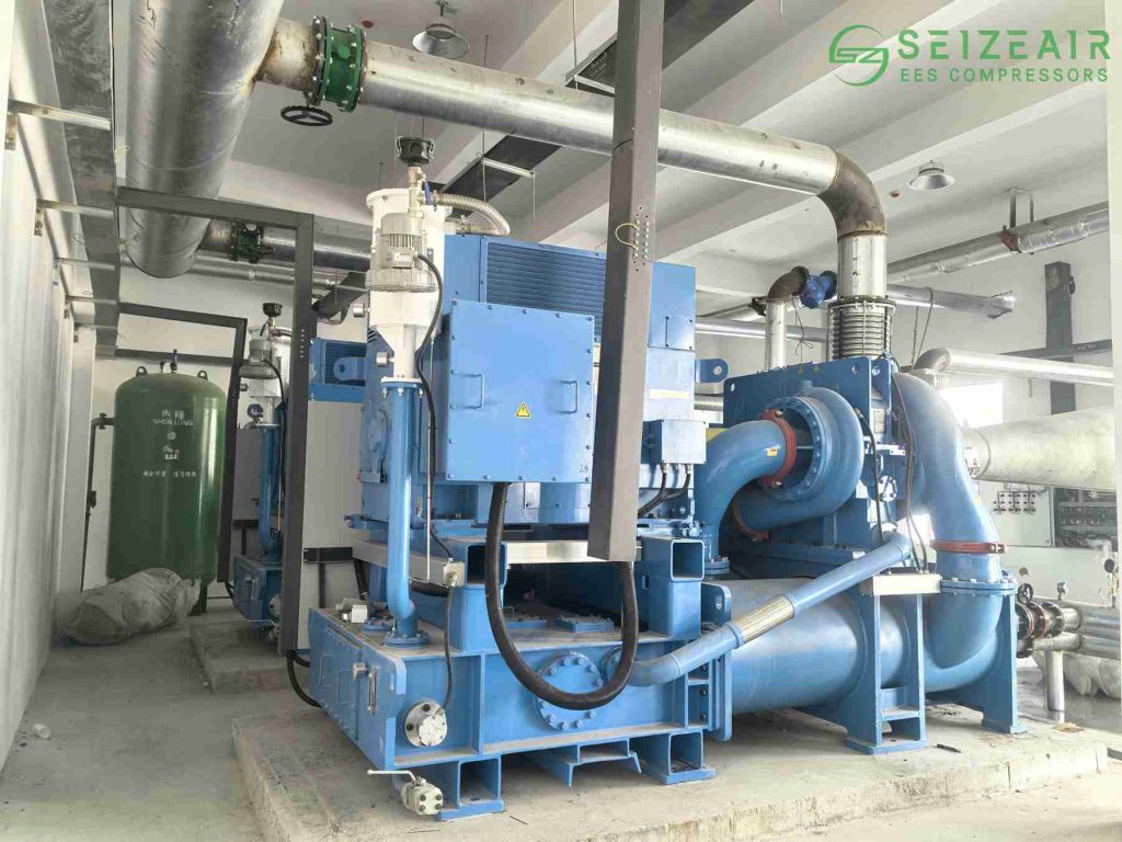
- Enclosed vs. Open Impellers: Enclosed (shrouded) impellers suit high-pressure gas applications to limit tip leakage losses. Open 3D-milled impellers handle high Mach number flows in first-stage applications.
- Metallurgy: Impellers use high-strength alloys including 17-4PH stainless steel, Inconel 718, or Titanium Grade 5 to withstand stress corrosion cracking (SCC) caused by sour gas (wet H2S).
2. Dry Gas Seal (DGS) Technology
Dry Gas Seals (DGS) have replaced older wet lube oil seals. DGS systems use non-contacting, spiral-grooved rotating rings separated by a thin gas film (3 to 5 microns) generated by dynamic forces.
- Eliminates seal oil contamination in process loops.
- Reduces fugitive methane emissions by over 95% when paired with seal gas recovery skids.
3. Active Magnetic Bearings (AMB) vs. Tilting Pad Bearings
While tilting pad hydrodynamic bearings remain common due to proven longevity, Active Magnetic Bearings (AMBs) are expanding in subsea and offshore platforms:
- Zero Lube Oil System: Removes oil skids, pumps, coolers, and reservoirs, cutting package weight by up to 30%.
- Lower Friction Losses: Eliminates mechanical contact, cutting parasitic drag and increasing overall machine efficiency.
For auxiliary instrument air, seal gas booster loops, and valve actuation, reliable utility delivery remains essential. Integrating Seize Air rotary screw air compressor skids alongside main process turbomachinery ensures clean, dry, instrument-grade compressed air supply that prevents control loop downtime.
How Can Operators Prevent Surge, Choke, and Vibration Failures?
Operating a high-speed centrifugal compressor outside its stable performance envelope can lead to dynamic instability and mechanical damage within seconds.
Understanding Surge and Anti-Surge Control Systems
Surge occurs when gas flow drops below a critical threshold for a given discharge pressure. The gas can no longer overcome downstream resistance, causing rapid flow reversal inside the impellers.
- Symptoms: Violent axial shaft displacement, severe piping vibration, rapid temperature spikes, and high dynamic bearing loads.
- Prevention: Fast-acting Anti-Surge Valves (ASV) bypass discharge gas back to the suction line through a cooling circuit when operating points approach the Surge Control Line (SCL).
Choke (Stonewall) Conditions
Choke occurs when gas velocity reaches sonic speed (Mach 1) at the impeller throat or diffuser inlet. Flow cannot increase further regardless of dropping downstream pressure, limiting overall system throughput.
Condition Monitoring & Predictive Maintenance
Operators install proximity probes and accelerometers to monitor vibration spectrums continuously:
- 1X Vibration: Unbalance in the rotating element.
- 0.45X–0.48X Sub-synchronous Vibration: Hydrodynamic oil whirl/whip inside journal bearings.
- High-Frequency Spikes: Aerodynamic instability, diffuser stall, or seal rubs.
What Are the Latest Decarbonization Trends for Centrifugal Compressors?
The shift toward lower emissions is changing how turbomachinery is specified and operated.
1. Carbon Capture, Utilization, and Storage (CCUS)
CO2 compression presents unique physical challenges. Near its critical point (73.8 bar, 31.1 degrees C), CO2 shifts from gas to a dense-phase fluid with sudden changes in density, compressibility, and speed of sound. Centrifugal CO2 compressors require specialized staging, dense-phase intercooling, and polymer seal materials resistant to rapid gas decompression (RGD).
2. Hydrogen Blending and Pure H2 Transport
As energy networks blend hydrogen into existing natural gas lines, centrifugal compressors must adjust for lower gas density and lighter molecular weights:
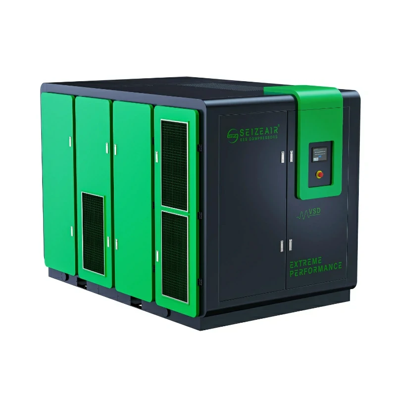
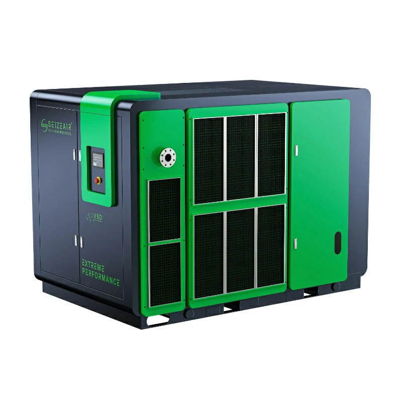
To lower plant carbon intensity, operators replace gas turbine drivers with high-efficiency VFD electric motors. When paired with energy-efficient site equipment—like Seize Air VFD utility air compressors—refineries reduce total electrical demand and lower overall carbon intensity scores.
What Is the Essential Maintenance Checklist for Centrifugal Compressors?
Preventive maintenance preserves aerodynamic performance and prevents unplanned trips.
- Daily Maintenance:
- Monitor dry gas seal primary vent pressure and leakage flow rate.
- Check lube oil supply pressure, temperature, and filter differential pressure.
- Review overall vibration trend graphs (X-Y radial proximity probes and axial displacement).
- Monthly Maintenance:
- Test anti-surge valve stroke speed and position feedback calibration.
- Sample lube oil for particulate contamination, viscosity loss, and water content.
- Inspect utility air quality entering pneumatic actuators and dry gas seal panels; keep air filters clean on site equipment provided by manufacturers like Seize Air.
- Turnaround / Major Overhaul (Every 3 to 6 Years):
- Perform complete rotor pull, non-destructive testing (NDT) on impellers, and dynamic balancing.
- Replace dry gas seal cartridges and internal labyrinth seals.
- Clean diffuser passages and remove internal casing fouling.
Frequently Asked Questions
What is the difference between an axial and centrifugal compressor in gas operations?
Centrifugal compressors move gas radially outward from the shaft center, generating high pressure ratios per stage (1.5:1 up to 3:1+). Axial compressors push gas parallel to the shaft through alternating rows of rotating and stationary blades. Axial units handle higher volumetric flow rates at lower pressure ratios per stage (1.1:1 to 1.4:1) and are used in large industrial gas turbines or main air separation plants.
How do operators prevent surge in centrifugal compressors during sudden flow drops?
Operators use automated anti-surge control systems linked to fast-acting Anti-Surge Valves (ASV). When flow approaches the Surge Control Line (SCL), the ASV opens within milliseconds to recycle discharge gas back to the suction line through a cooling circuit, maintaining minimum volumetric flow through the impellers.
Why are dry gas seals used instead of wet lube oil seals in API 617 centrifugal compressors?
Dry Gas Seals eliminate complex seal oil skids, pumps, and contaminated oil disposal systems. They cut fugitive methane gas emissions by over 95%, eliminate oil contamination in process gas lines, reduce parasitic power losses, and extend operating intervals between overhauls.
How does gas molecular weight change affect centrifugal compressor polytropic head?
Polytropic head is inversely proportional to gas molecular weight. Lighter gases (like hydrogen) require significantly more energy, higher impeller tip speeds, or additional impeller stages to achieve the same pressure ratio compared to heavier gases (like propane or CO2).
Optimizing Your Compression Facilities with Expert Support
Selecting, integrating, and maintaining compression assets requires balancing aerodynamic performance, metallurgy, sealing systems, and drive controls. Beyond primary process compressors, maintaining reliable, clean instrument air is crucial for keeping anti-surge valves, seal gas control skids, and field instrumentation operating without failure.
If you are upgrading field air systems, designing gas processing infrastructure, or replacing old utility equipment, working with experienced turbomachinery and air management specialists ensures maximum lifecycle efficiency.
Ready to enhance your plant reliability and optimize utility air performance? Contact our technical engineering team at Seize Air today to discuss your field requirements, request detailed product specifications, or schedule an equipment assessment with our compressed air system specialists.