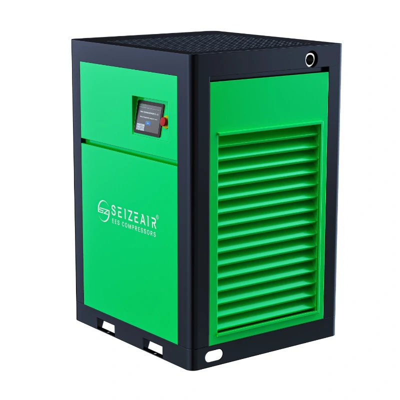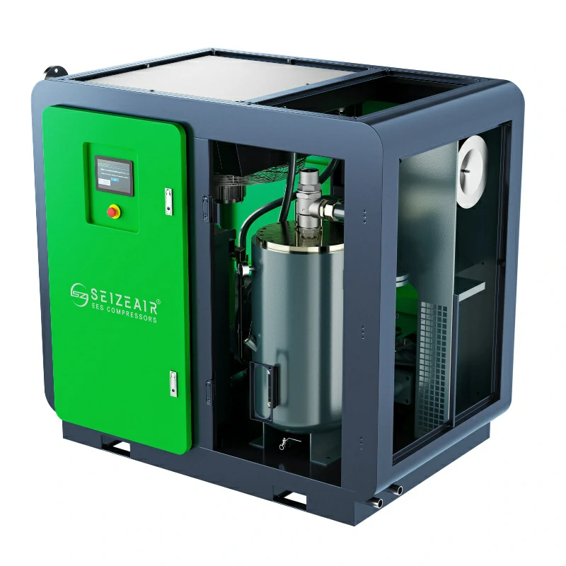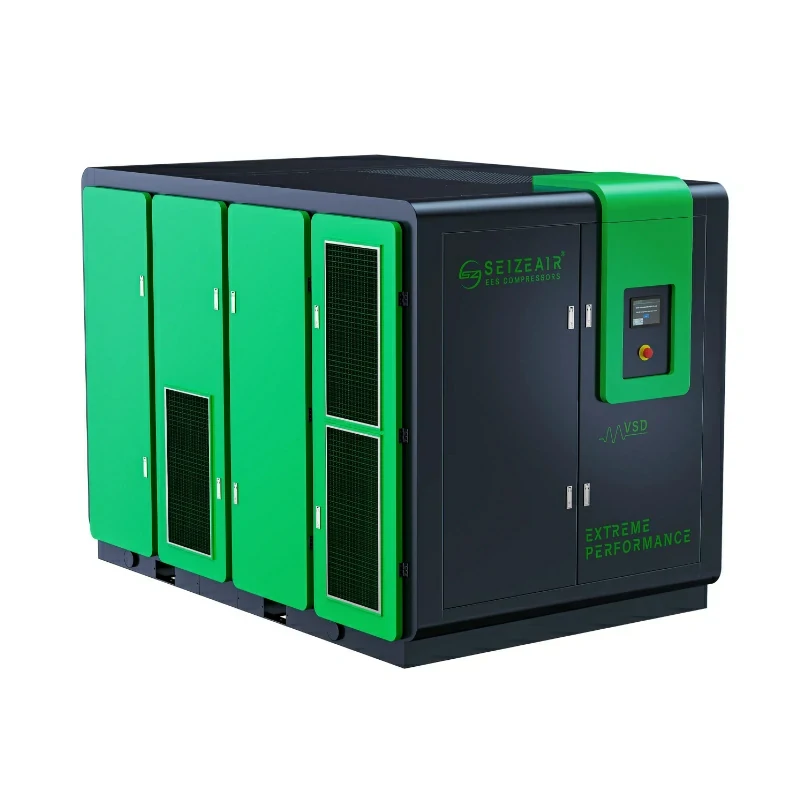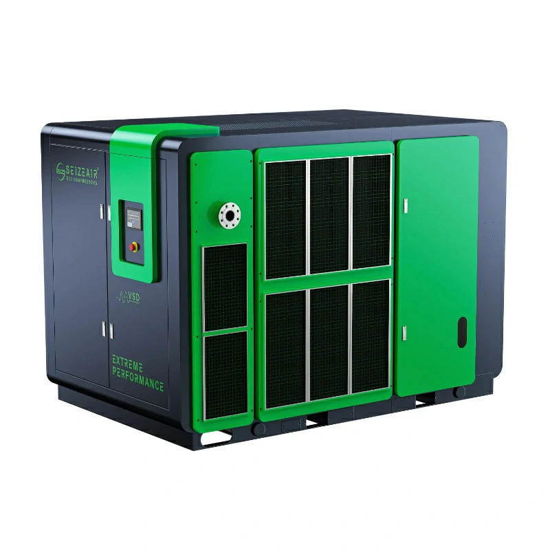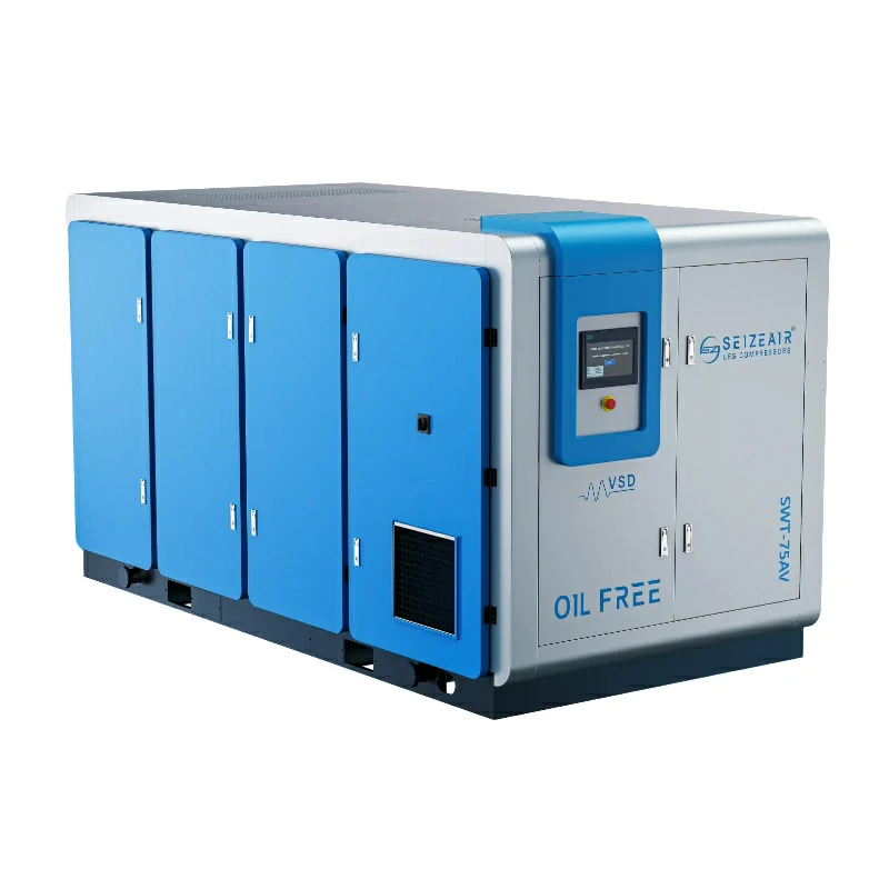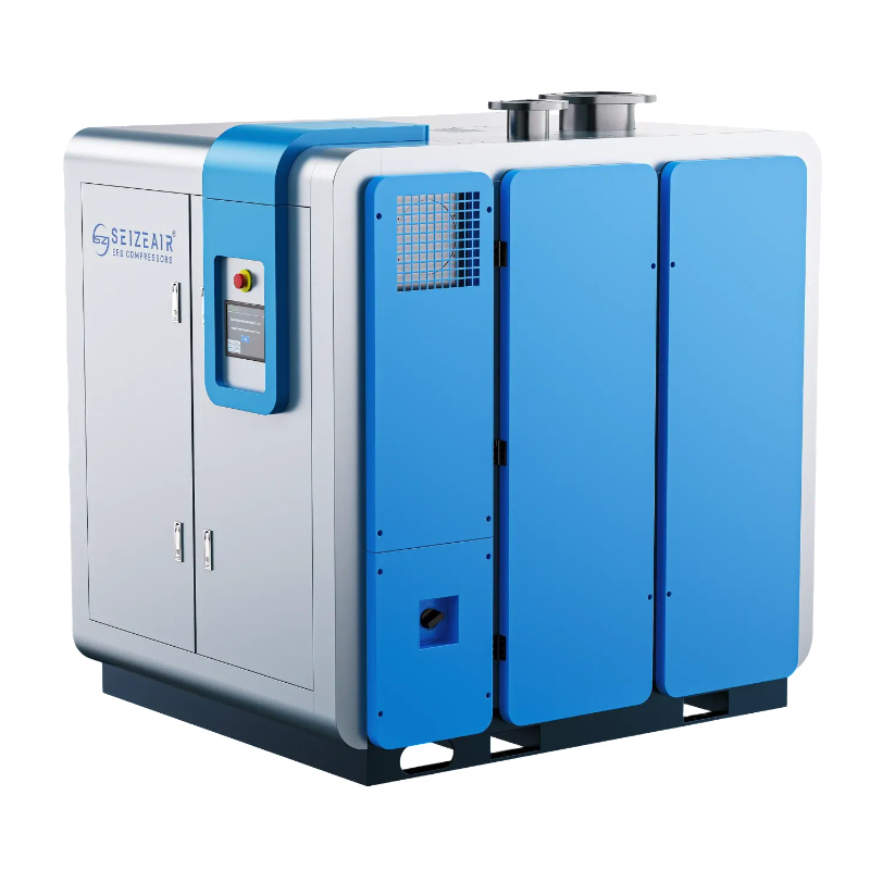


Looking for the best air compressor for textile industry operations to secure zero-oil yarn quality and cut plant electricity costs? Compressed air is the essential fourth utility in modern textile manufacturing—powering high-speed air-jet looms, pneumatic spinning frames, automated dyeing valves, and precision garment finishing lines. Choosing the right energy-efficient oil-free compressor prevents fabric contamination, eliminates sudden line pressure drops, and lowers your monthly operating overhead.
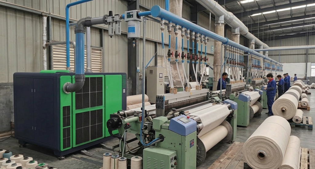
What Air Purity Standard Is Required for Air-Jet Looms and Spinning?
In modern textile production, compressed air comes into direct contact with raw fibers, delicate yarns, and sensitive pneumatic control networks. Understanding the strict air purity standards required for these applications prevents costly production line errors.
+-----------------------------------------------------------------------+
|                 TEXTILE FACTORY AIR SUPPLY DISTRIBUTION                |
+-----------------------------------------------------------------------+
|                                                                       |
|  [ COMPRESSOR STATION ]                                               |
|           |                                                           |
|           +---> [ Air-Jet Weaving ] -----> Direct yarn contact        |
|           |                                (Requires ISO Class 0 Oil) |
|           |                                                           |
|           +---> [ Spinning & Carding ] --> Pneumatic pressure arms    |
|           |                                                           |
|           +---> [ Dyeing & Finishing ] --> Valve actuation & drying   |
|           |                                                           |
|           +---> [ Garment Manufacturing ] -> Pneumatic cutters & sewing|
+-----------------------------------------------------------------------+
Critical Textile Applications and Quality Protocols
- Air-Jet Weaving Weft Insertion: Main and auxiliary relay nozzles blast compressed air through the shed at speeds up to 1,200 ppm (picks per minute). Any trace of liquid oil or vapor stains the yarn, clogs micro-nozzle orifices, alters yarn tension, and causes continuous reed stops.When a single relay nozzle clogs with oily varnish, it fires late by just milliseconds. That fraction of a second is enough to drop the weft thread, tripping the loom’s optical sensor and triggering an emergency stop. If you run 200 looms in a shed and average three oil-related stops per loom every shift, you aren’t just losing output—you’re destroying worker productivity as weavers spend half their shift clearing micro-stalls instead of managing beam changes.
- Spinning and Carding Operations: Pneumatic drafting arms, automatic piecing systems, and rotor spinning units require continuous, surge-free pressure. Minor pressure fluctuations cause drafting errors, leading to weak spots, uneven linear density, and yarn breakage.If header pressure drops even 0.4 bar below setpoint during a shift change, the top-roller loading arms lose uniform clamping force. The drafting aprons slip against the roving, creating thick and thin spots across thousands of spindles simultaneously. By the time quality control catches the mass variation on the Uster tester, you’ve already wound tens of thousands of meters of out-of-spec yarn onto bobbins that will fail downstream tensile tests.
- Dyeing, Printing, and Bleaching: Pneumatic control valves regulate dye dosing, steam injection, and fluid temperature. Moisture in supply lines causes internal valve oxidation, sticky actuator seats, and imprecise chemical dosing, leading to shade variations across fabric batches.System integrators often see plants waste hundreds of thousands of dollars troubleshooting “faulty” batch dyeing equipment, only to realize the root cause is water in the instrument air headers. When condensed moisture coats the internal seals of a proportional control valve, the valve stutters rather than smoothly metering dye liquor. A 2% error in chemical dosing caused by a sticking pneumatic valve changes the Delta-E color value enough to reject an entire 500-meter batch of finished silk or high-end synthetic fabric.
- Automated Garment Production: Automatic cutting tables, pocket setters, and steam pressing machines depend on dry, particle-free air for smooth pneumatic cylinder cycles and long solenoid valve life.High-speed vacuum cutting heads rely on precision pneumatic actuators operating under high cycle frequencies. If airborne pipe scale or wet sludge enters these compact valve manifolds, internal spools bind up, causing misaligned pattern cuts through multi-layer fabric stacks.
Why Is an Oil-Free Compressor Essential for Textile Manufacturing?
Using the wrong compressed air system triggers immediate operational issues and long-term financial loss across your weaving and spinning floors.
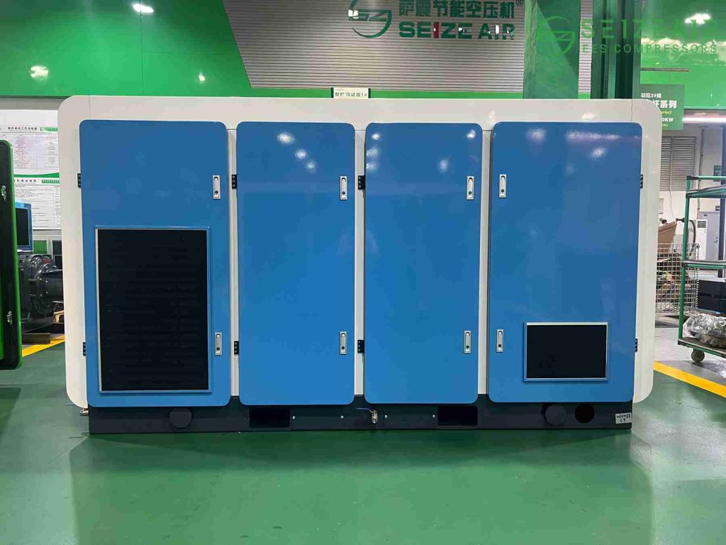
- Fabric Oil Stains and Rejection Rates: Microscopic oil mist from oil-lubricated compressors passes through conventional line filters over time. Oil droplets settle on raw yarn and grey fabric during air-jet insertion. These oil spots resist water-based dyes, resulting in permanently ruined fabric, elevated scrap rates, and labor-intensive chemical spot-cleaning.Here is a hard truth from plant floor experience: coalesce filters on oil-injected units fail gradually, not suddenly. The internal element becomes saturated, differential pressure rises, and oil aerosol quietly starts bypassing the media. By the time operators notice yellowish spots under inspection lamps on finished white cotton rolls, days of production are contaminated. You end up selling prime-grade fabric as B-grade scrap at a 40% discount, destroying your operating margins.
- Nozzle Clogging and Micro-Pneumatic Failure: Water vapor mixed with ambient airborne lint creates a sticky slurry inside distribution pipes. This slurry clogs air-jet loom main nozzles, coats pneumatic solenoid valves, and corrodes internal cylinder walls, increasing spare part consumption and emergency downtime.When wet air combines with fine cotton fly inside air mains, it bakes onto hot valve surfaces and transforms into a cement-like sludge. The solenoid valves controlling your loom relay nozzles suffer accelerated seal wear and coil burnouts. Instead of replacing valve blocks every five years during scheduled overhaul windows, plant technicians end up swapping out degraded valve manifolds every eight to twelve months.
- Surging Energy Bills and Utility Expenses: Compressed air accounts for 10% to 20% of total electrical power consumed in a typical textile plant. Running an inefficient, oversized, or improperly controlled compressor system wastes tens of thousands of dollars annually in unnecessary electricity costs.If you look at the factory balance sheet, electricity is usually the second highest operating expense after raw fiber input. A 250 kW compressor idling at 70% power during low-demand periods burns through real capital without producing a single CFM of useful work. Modern plant managers realize that cutting compressor Kw-hours directly boosts gross operating margin faster than fighting for tiny supplier discounts on raw yarn.
How to Choose the Best Air Compressor Technology for Textile Mills?
Choosing the right technology requires matching compressor performance characteristics with your plant’s continuous demand profile and air quality targets.
| Compressor Type | Pressure Range | Flow Capacity (CFM) | Best Suited For | Key Advantages |
| Dry Oil-Free Rotary Screw Compressor for Textile Weaving | 7 – 10 bar | 100 – 1,500 CFM | Medium to Large Mills (Weaving & Spinning) | 100% oil-free air, reliable continuous duty |
| Centrifugal Air Compressor for Large Textile Mills | 7 – 12 bar | 1,500 – 10,000+ CFM | Mega Textile Complexes & Fiber Plants | High base-load efficiency, low maintenance |
| Oil-Injected Rotary Screw Air Compressor | 7 – 13 bar | 20 – 1,000 CFM | General Plant Utilities (Non-fabric contact) | Lower upfront capital cost, rugged design |
| Variable Speed Drive VSD Screw Air Compressor for Textile Plant | 4 – 10 bar | Dynamic Flow | Mills with fluctuating shift demand | Up to 35% power savings, smooth soft-starting |
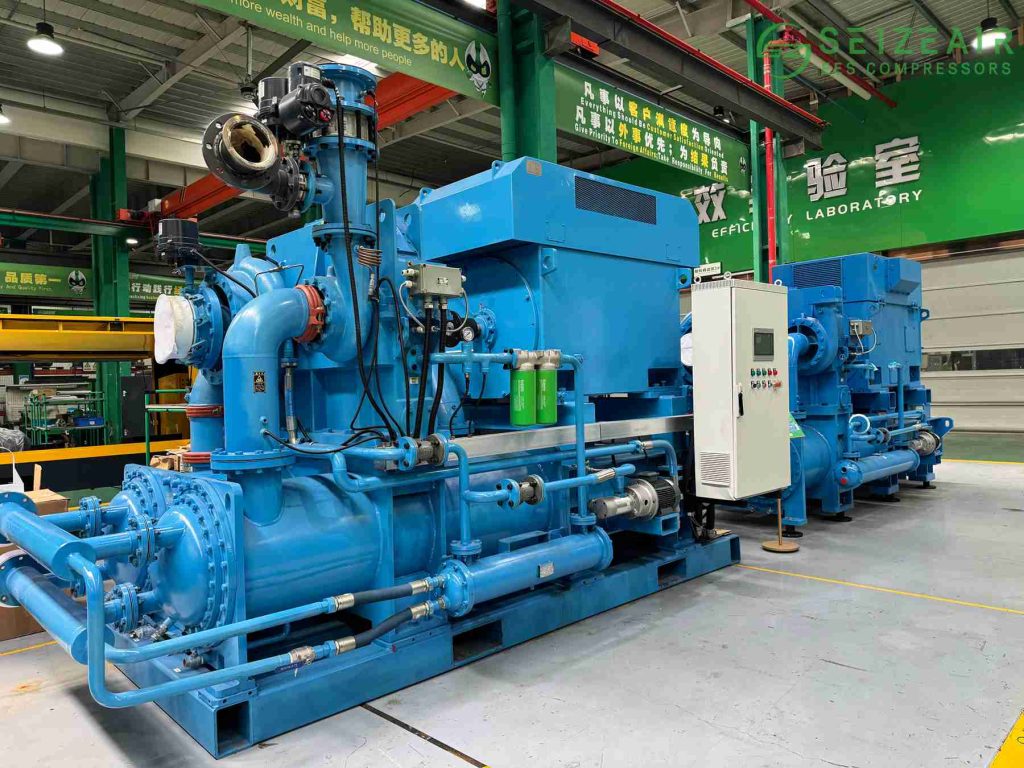
ISO 8573-1 Class 0 Oil-Free vs. Oil-Injected Systems
- ISO 8573-1 Class 0 Oil-Free Compressors: Engineered without oil in the compression chamber. They eliminate oil contamination risks at the source, guaranteeing 100% pure air for air-jet weaving, high-count ring spinning, and texturing processes.From an engineering standpoint, oil-free rotary screw elements rely on specialized PTFE or carbon-based rotor coatings and precision timing gears to maintain ultra-tight tolerances without physical metal-to-metal contact. Because no oil is injected into the compression pocket to absorb the heat of compression, these units utilize jacketed water or dual-stage intercooling to dissipate heat efficiently. This design guarantees zero hydrocarbon transfer into the discharge air, ensuring absolute compliance with Class 0 standards regardless of filter wear downstream.
- Oil-Injected Rotary Screw Compressors: Rely on oil within the rotor housing for cooling, sealing, and lubrication. While suitable for maintenance workshops and general mechanical drives, using them near yarn or fabric carries inherent risk, even with downstream coalescing filters and carbon towers.Plant engineers often fall into the trap of looking only at initial capital expenditure (CAPEX). An oil-injected compressor setup appears significantly cheaper on a purchase order compared to a dry oil-free system. But when you factor in the lifetime replacement costs of multi-stage coalescing filters, activated carbon beds, hazardous condensate disposal services, and the continuous pressure drop penalty across those extra filter housings, the lifecycle cost of an oil-injected system in a weaving shed easily surpasses an oil-free platform within 3 to 4 years of continuous operation.
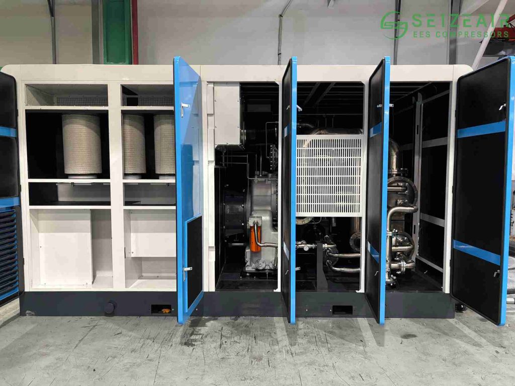
For complete operational safety and continuous output, manufacturers like Seize Air recommend dedicated Class 0 dry oil-free rotary screw platforms built specifically to withstand high-ambient, high-dust textile environments.
How to Calculate CFM and Pressure Requirements for Air-Jet Looms?
An accurate, step-by-step air sizing calculation prevents buying excess horsepower or suffering pressure drops during peak shift transitions.
+-----------------------------------------------------------------------+
|                      AIR AUDIT CALCULATION STEPS                      |
+-----------------------------------------------------------------------+
|                                                                       |
|  [ Total Tool CFM ] + [ Leakage Allowance (10-15%) ]                  |
|                        |                                              |
|                        v                                              |
|  [ Base CFM Needed ] x [ Safety Factor (1.20) ]                       |
|                        |                                              |
|                        v                                              |
|  [ FINAL REQUIRED COMPRESSOR CAPACITY ]                               |
+-----------------------------------------------------------------------+
Step 1: Calculate Total Air Consumption Volume (CFM / m3/min)
Audit every air-consuming machine across your production line and sum their required Cubic Feet per Minute (CFM) or cubic meters per minute (m3/min).
- Sample Air-Jet Loom Calculation:
- A single high-speed air-jet loom running at 800 RPM on cotton yarn consumes approximately 25 to 35 CFM depending on reed width and insertion timings.
- For a shed operating 60 air-jet looms at an average of 28 CFM each:
- Base Loom Air Requirement = 60 x 28 = 1,680 CFM
- When engineering the supply line, always check whether your mill runs complex dobby or jacquard weaves. Jacquard looms require additional auxiliary air blasts for harness cooling and pattern selector mechanisms, which can add another 3 to 5 CFM per machine onto your base baseline calculations.
Step 2: Account for Pipe Network Leakage
Industrial textile piping loops experience natural pressure loss and minor leakage through aged fittings, flexible hose connections, and valve seats over time.
- Add a standard 10% to 15% leakage allowance to your base demand calculation.
- Leakage-Adjusted Airflow = 1,680 CFM x 1.15 = 1,932 CFM
- In real-world textile facilities operating 24/7, ambient plant vibration from hundreds of looms constantly loosens quick-connect fittings and valve threads. A system audit on a 10-year-old piping loop frequently reveals leak rates exceeding 25% if maintenance teams do not perform quarterly ultrasonic leak detection sweeps.
Step 3: Apply System Expansion and Safety Margin
- Multiply by a 1.15 to 1.20 safety margin to handle temporary demand spikes, simultaneous jet blowing, and future loom additions.
- Final Required Compressor Capacity = 1,932 CFM x 1.20 = 2,318.4 CFM (65.6 m3/min)
- Selecting a compressor that operates continuously at 100% full load capacity leaves zero buffer for ambient temperature heat derating during summer months. Maintaining a 15-20% capacity headroom ensures the system runs within its optimal efficiency sweet spot without thermal trips.
Target Discharge Pressure Calculation (PSI / Bar)
System pressure must match the highest machine operating requirement on the floor plus all downstream friction drops:
Required Compressor Discharge Pressure = Maximum Loom Inlet Pressure + Line & Filter Pressure Losses
- If your air-jet looms demand 6.0 bar (87 PSI) clean pressure at the machine inlet manifold:
- Air Dryer and In-Line Filter Drops: 0.5 bar
- Piping Friction & Rise Loss: 0.3 bar
- Target Compressor Pressure = 6.0 + 0.5 + 0.3 = 6.8 bar (~100 PSI)
- Remember that every additional 1 bar (14.5 PSI) of pressure created at the compressor discharge increases motor power consumption by roughly 7%. Oversizing system operating pressure just to compensate for undersized distribution piping is one of the most expensive design errors a factory can make.
Which Features Are Crucial in a Textile Factory Compressed Air System?
Evaluating commercial models requires looking past basic nameplate motor ratings to prioritize features designed for textile manufacturing conditions:
1. Inverter-Driven Variable Speed Drive (VSD) Control
Air consumption in textile mills varies constantly based on style changes, yarn pick density, loom downtime, and shift changes. Fixed-speed air compressors waste substantial electricity when unloading and idling during lower demand periods. A VSD air compressor dynamically adjusts motor RPM to match exact real-time air demand, cutting electrical energy usage by 25% to 35%.
When integrating a central compressor house, pairing a fixed-speed base-load compressor with a VSD trim compressor delivers the absolute lowest specific energy consumption (kW per 100 CFM). The fixed-speed machine handles the constant minimum base air demand of the loom shed, while the VSD unit smoothly tracks real-time load swings as looms start and stop across the floor.
2. High Ambient Temperature and Heavy Lint Air Filtration
Spinning and weaving sheds are warm, dust-dense environments filled with airborne fiber fly and fine cotton dust. Reliable air compressors for this setting require:
- Over-sized cooling radiators rated for continuous duty in ambient temperatures up to 45°C to 50°C.
- Multi-stage intake air filter enclosures with pre-filter mats to capture airborne lint and fly before it coats internal coolers or rotor air ends.Standard off-the-shelf industrial compressors often struggle in textile environments because airborne cotton fly quickly blinds standard radiator fins. Once air coolers become blanketed in lint, discharge air temperatures skyrocket, causing thermal trips during peak summer afternoons. Heavy-duty units built specifically for textile mills feature wide-fin heat exchangers coupled with reverse-blowing fans that purge accumulated lint automatically.
3. Integrated Thermal Energy Recovery Systems
Up to 94% of the electrical energy consumed by an industrial air compressor transforms into thermal heat during compression. Modern heat recovery systems capture this waste heat directly from oil and cooling circuits, delivering hot water (up to 70°C – 80°C) directly to your dyeing, bleaching, fabric washing, and boiler feed water processes, reducing boiler fuel consumption.
From an economic standpoint, installing heat recovery exchangers yields a surprisingly rapid ROI. If your plant burns natural gas or heavy fuel oil to heat water for batch dyeing vats, routing compressor waste heat into your warm water holding tanks slashes thermal utility bills immediately, transforming an overhead power expense into useful process heat.
Heavy-duty models engineered by Seize Air feature custom-built thermal recovery modules and smart inverter controllers specifically designed to optimize seasonal Energy Efficiency Ratio (EER) inside demanding textile production plants.
What ISO Air Quality Class Is Needed for Textile Mills?
Air purity requirements vary by department and proximity to raw materials, as defined by international standard ISO 8573-1:2010:
| Process / Department | Solid Particles (Class) | Water Moisture (Class) | Oil Content (Class) | Recommended Dew Point |
| Air-Jet Weaving Sheds | Class 2 (<= 1 micron) | Class 4 (+3°C PDP) | Class 0 (0 mg/m3) | +3°C (Refrigerated) |
| Ring & Rotor Spinning | Class 2 (<= 1 micron) | Class 4 (+3°C PDP) | Class 0 (0 mg/m3) | +3°C (Refrigerated) |
| General Mill Utilities | Class 4 (<= 15 micron) | Class 4 (+3°C PDP) | Class 2 (0.1 mg/m3) | +3°C (Refrigerated) |
| Outdoor Air Lines | Class 2 (<= 1 micron) | Class 2 (-40°C PDP) | Class 1 (0.01 mg/m3) | -40°C (Desiccant) |
Different sections of a textile plant require distinct air treatment strategies. Trying to apply a blanket air treatment specification across the entire facility usually results in either under-treating sensitive process lines or over-treating general utility air.
For instance, feeding raw utility air into air-jet weaving manifolds causes rapid nozzle degradation, while installing sub-zero desiccant drying systems on general shop maintenance lines inflates operational purge air losses unnecessarily. Smart plant design segregates air headers by application, optimizing filtration costs per cubic meter.
How to Setup Downstream Air Treatment for Weaving and Spinning?
Installing a reliable oil-free compressor is only the first step. Downstream air treatment equipment ensures air arrives at your production machinery at the target pressure dew point and particle level.
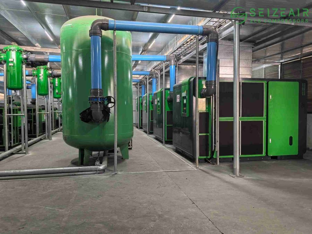
+-----------------------------------------------------------------------+
|                    RECOMMENDED DOWNSTREAM PIPELINE                    |
+-----------------------------------------------------------------------+
|                                                                       |
| [ Compressor ] --> [ Wet Receiver ] --> [ Pre-Filter ]                |
|                                                |                      |
|                                                v                      |
| [ Dry Receiver ] <-- [ Dust Filter ] <-- [ Air Dryer ]                |
|         |                                                             |
|         +---> [ Air Distribution Pipeline to Loom Shed ]              |
+-----------------------------------------------------------------------+
- Wet Air Receiver Vessel: Acts as a thermal buffer, dampening pressure pulsation while knocking out bulk liquid condensate before air hits downstream dryers.Positioning a wet receiver before the dryer allows hot discharge air to expand and cool naturally, dropping out up to 60% of entrained liquid moisture through a mechanical auto-drain. This significantly reduces the thermal moisture load placed on the refrigerated air dryer, extending its service life and lowering energy consumption.
- Heavy-Duty Pre-Filter: Traps particulate solids down to 1-3 microns, preventing scale and dust from fouling downstream dryer heat exchanger surfaces.
- Energy-Efficient Refrigerated Air Dryer: Drops air temperature down to a +3°C pressure dew point, condensing remaining water vapor into liquid water for auto-draining.Always specify air dryers equipped with digital scroll technology or variable-speed refrigeration compressors rather than hot-gas bypass models. Non-cycling refrigerated dryers run their cooling compressors at 100% power regardless of air throughput, whereas cycling models scale cooling power directly with real-time airflow, saving substantial electrical power during off-peak hours.
- Heatless Desiccant Air Dryer (Optional): Essential for outdoor air distribution headers exposed to freezing seasonal weather, driving pressure dew points down to -40°C.If your facility routes main air headers across open yards between buildings in cold climates, standard refrigerated dryers will not prevent line condensation. Uninsulated outdoor pipes drop below the +3°C dew point in winter, creating interior ice buildup, pressure drops, and slugs of water at distant drop points. A desiccant system prevents these seasonal moisture disasters.
- Micro-Particulate Line Filters: Mounted directly at loom header drops to eliminate micro-particles down to 0.01 micron before air reaches air-jet valves and solenoids.
How Much Air Does an Air-Jet Loom Consume Per Minute?
An air-jet loom consumes 20 to 35 CFM (0.6 to 1.0 m3/min) of compressed air under typical operating conditions. Actual consumption varies based on loom operating speed (RPM), fabric width, yarn weight, and whether single or dual auxiliary main nozzles are used for weft insertion.
To put this into practical perspective, a large-scale weaving plant running 300 modern air-jet looms at high speeds will demand between 7,500 and 10,500 CFM of continuous, clean compressed air. At this scale, even a tiny 0.1 bar reduction in pressure drop across your main distribution header yields massive annually compounded electricity savings across your central compressor room.
What Is the Total Cost of Ownership for Textile Air Compressors?
When evaluating an air compressor for textile industry installation, the initial purchase price accounts for only a small portion of your total lifecycle expenditure over a 10-year period.
Total Cost of Ownership Breakdown (10-Year Lifecycle):
+-------------------------------------------------------+
| Electricity / Energy Consumption :  70% - 80%        |
| Scheduled Maintenance & Servicing:  10% - 15%        |
| Initial Capital Purchase Price   :  10% - 15%        |
+-------------------------------------------------------+
Calculating Total Cost of Ownership (TCO) reveals why buying compressed air equipment based solely on lowest initial purchase price is a dangerous trap for financial managers. Over ten years of 24/7 continuous operation, a typical 200 kW industrial compressor will consume electrical energy worth six to eight times its original purchase price.
When you evaluate bids from equipment suppliers, look closely at specific power performance curves (kW per 100 CFM delivered at operating pressure) validated by ISO 1217 Annex C/E testing standards. A compressor model that costs $15,000 more upfront but delivers a 5% improvement in specific power consumption will fully recover that purchase price differential in energy savings within its first year of full-time operation.
Choosing a high-efficiency VSD compressor backed by regional service support from manufacturers like Seize Air pays back the initial capital difference within 12 to 24 months strictly through reduced monthly utility bills and zero oil-stained yarn scrap.
Lower Your Textile Plant Power Consumption with Expert Air Systems
Selecting the ideal compressed air system involves balancing airflow volume, working pressure, air purity, and long-term energy consumption. Tailoring your air room to your mill’s specific demands protects yarn quality, eliminates unplanned downtime, and lowers overall utility bills month after month.
Whether you are expanding an air-jet weaving shed, modernizing a spinning line, or auditing plant energy performance, an on-site compressed air audit provides a clear path forward.
Ready to lower energy consumption and protect your textile quality?
Contact the technical application team at Seize Air today. Our industrial compressed air specialists will evaluate your actual air demand, analyze your quality requirements, and design a custom, energy-efficient compressed air solution engineered specifically for your textile operation.
- Whatsapp:+8618348031303
- Email: info@seize-air.com