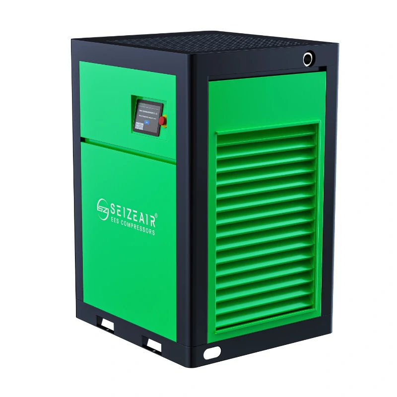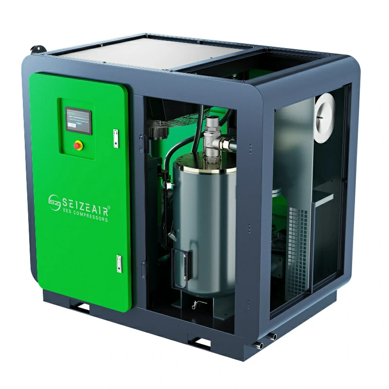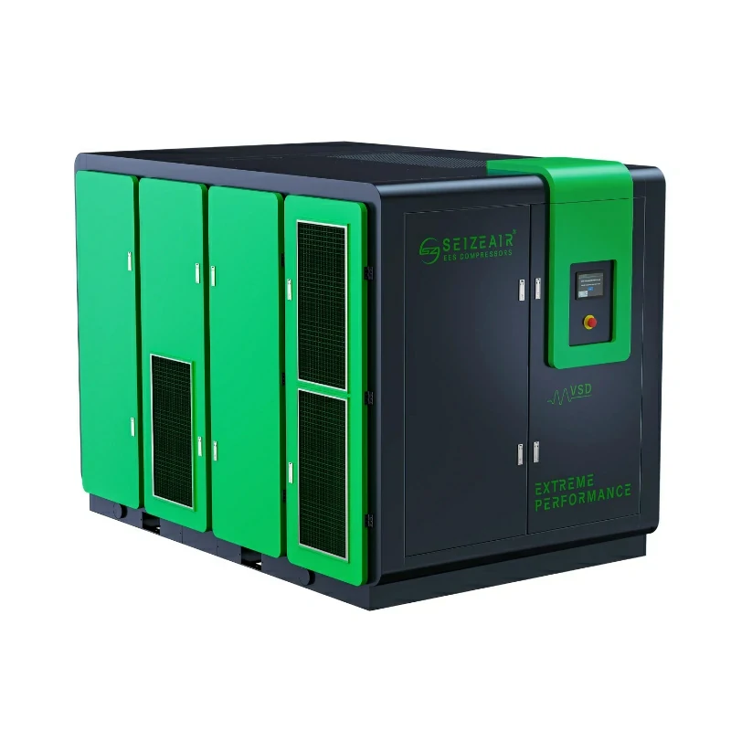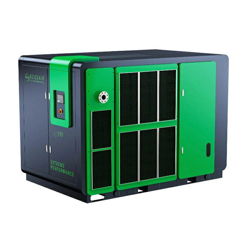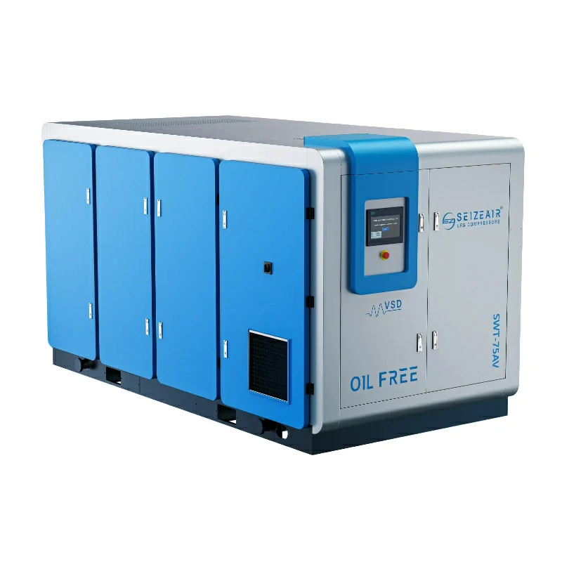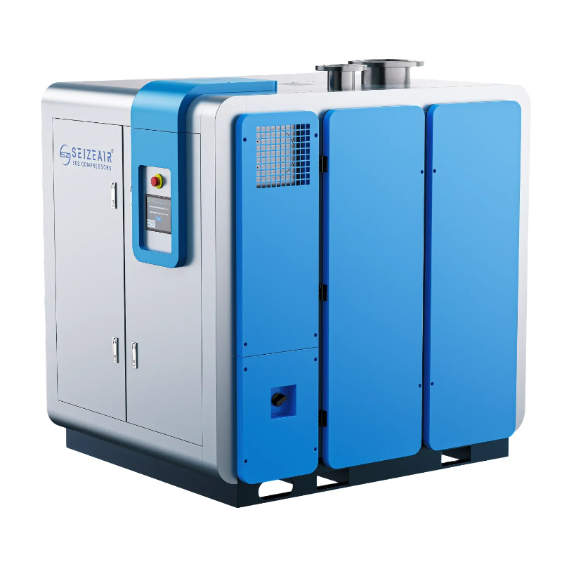


An air compressor for electronics industry duty is judged by exactly one thing, and it has nothing to do with how many bar it makes. It is judged by what lands on the product after the air leaves the nozzle. This guide covers what oil-free really guarantees, how to read ISO 8573-1 purity classes for PCB assembly lines, semiconductor tools and cleanrooms, how to size capacity and drying realistically, how compressor room layout quietly decides your air quality, and what the whole thing costs to own.
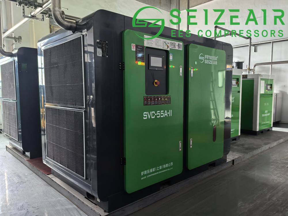
Why Clean Compressed Air Is Non-Negotiable in Electronics Manufacturing
Electronics assembly is one of the few industries where compressed air touches the product surface itself. It drives the vacuum generators on pick-and-place heads, powers the pneumatic actuators on dispensers, crimpers and test handlers, blows excess residue off stencils, feeds the ionising blowers used for static control, and supplies the clean dry air network that fab tools use for wafer handling, chamber venting and valve actuation.
Each of those uses puts the contents of your piping in direct contact with a surface that will later be soldered, bonded, coated or measured. A hydrocarbon film ten molecules thick is invisible on a copper pad, but it changes surface energy. Solder stops wetting evenly, conformal coating pulls back into beads instead of flowing flat, wire bonds lose pull strength, and adhesive joints fail months later in the field instead of at your test station. The reported symptoms come back as intermittent contact resistance, dendrite growth under humidity, or “random” early returns that never trace back to the compressor room.
Particles do their damage mechanically. A metal chip or desiccant dust grain larger than about a micron can plug the 0.5 mm or 0.7 mm bore of a placement nozzle, drop a component mid-cycle, or sit on a photomask. On a line running tens of thousands of placements per hour, one imbalance of that kind costs more than the difference between a budget compressor and a premium one.
Water behaves differently again. Compressed air carries whatever humidity got past the dryer, and free water appears wherever the air cools afterwards: in a long pipe run through an unheated void, across a regulator where the pressure drop chills the stream, or at an open blow-off nozzle where the expansion does the cooling. Water plus flux residue plus a few volts of bias is the textbook recipe for electrochemical migration. Root cause teams almost always start with materials and reflow profiles; it takes a dew point log before anybody questions the utility.
There is also a production rhythm argument. Modern electronics operations run three shifts with narrow changeover windows, so there is no slack time for rework caused by a utility. Air quality problems show up as a slow upward drift in defect rate rather than a clean failure you can schedule around, which makes them more expensive than most equipment failures with the same nominal impact.
This is why experienced buyers in this sector specify air quality first and kilowatts second, and why the real question has shifted from “what size air compressor do I need” to “which purity class does my process require, and can this configuration still meet it in August with the dryer regenerating and the plant at full load”.
What “Oil-Free” Means for an Air Compressor in Electronics Industry Applications
Oil-free is a claim about the compression chamber, not a claim about the delivered air. An oil-free machine introduces no lubricant into the air being compressed, so the air end itself cannot add oil. What it cannot do is remove oil already present in the intake air, and every plant sitting in an industrial park has measurable hydrocarbon vapour in its ambient air. Typical values run between roughly 0.05 and 0.5 mg per cubic metre depending on vehicle traffic, solvents used nearby, and neighbouring exhaust stacks. A diesel forklift idling under the intake will push local numbers well past that.
ISO 8573-1 handles this honestly. Class 0 exists precisely because “absolutely zero” is not measurable in a practical sense, so Class 0 is defined as stricter than Class 1 and agreed between user and supplier, with the test method stated. A real Class 0 claim is therefore a measured result at a defined location under defined conditions, backed by sampling carried out to ISO 8573-2 for oil aerosol or ISO 8573-5 for oil vapour. Anything less is a brochure line, and brochure lines do not hold up in an audit.
The distinction becomes decisive when you compare technologies. An oil-free screw air compressor with dry-running rotors eliminates the lubricant source completely; there is nothing downstream waiting to degrade. A conventional oil-injected screw fitted with coalescing filters and an activated carbon stage can also deliver technically oil-free air, and plenty of plants run exactly that successfully, but performance then depends on the filter from that point forward. The second route is cheaper to buy and more expensive to police, because quality slides between element changes and nobody notices until the defect rate moves.
| Term | What it actually guarantees | What it does not guarantee |
|---|---|---|
| Oil-free compression chamber | No lubricant touches the air end, so the machine adds no oil | Anything about ambient hydrocarbons pulled in at the intake |
| Technically oil-free delivered air | Measured oil below an agreed limit at a named sampling point | Performance once the filter medium passes its design life |
| ISO 8573-1 Class 0 | Stricter than Class 1, individually specified and verified | Water removal, particle removal, and anything inside the pipework |
| Oil Class 1 (0.01 mg/m3) | A defined numerical limit including vapour and aerosol | Anything about the particle or dew point class of the same air |
| “Class 0 certified” wording only | That a certificate exists | Where it was measured, by what method, or whether it still holds |
If one idea survives from this section, let it be that you specify the delivered air rather than the machine. Write the three-number purity class into the technical enquiry, name the sampling point, require test reports at commissioning, and require periodic re-verification for the life of the asset.
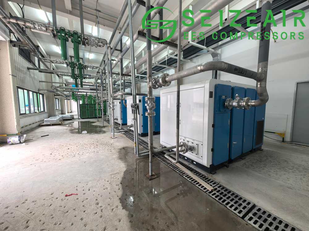
How Oil Contamination Damages SMT Lines, PCB Assembly and Wafer Tools
Understanding failure mechanisms has real troubleshooting value, because each mechanism leaves a recognisable signature on the board. Once you know the pattern, three minutes at a microscope points you back toward air quality instead of toward a three-week materials investigation.
Solder joints and wetting defects
Hydrocarbons on a pad or a lead act as a barrier layer. During reflow the molten alloy cannot displace it cleanly, so you see dewetting, un-wetted crescents at pad edges, or solder balling where the alloy retreats from copper it never bonded to. Flux chemistry is designed to strip oxides, not hydrocarbon films, so switching to a stronger flux rarely solves it and often introduces corrosion problems of its own. On fine pitch parts the same mechanism produces head-in-pillow defects, where the ball and the printed paste never coalesce. IPC-A-610 treats dewetting as a defect precisely because these joints can pass in-circuit testing today and then fail after a thousand thermal cycles.
Conformal coating, bonding and lamination
Coating adhesion failure is the slow-motion version of the same story. The coating goes down looking perfect, then lifts in patches after humidity testing or after a summer in the field. Acrylic, urethane and silicone coatings all depend on predictable surface energy; a monomolecular oil layer is enough to compromise it. Structural adhesives in display lamination and die attach materials in packaging behave no differently, and both are expensive places to discover contamination.
Vacuum pickup, nozzles and motion control
Placement heads generate vacuum through small ejectors fed by compressed air. Oil mist and fine solids accumulate in the ejector throat and nozzle bore, pulling vacuum level down until components get dropped or skewed. In most plants this is diagnosed as nozzle wear, and for a while replacing nozzles does fix it, until the new set fouls as well. Downstream of that, air bearings, air slides and pneumatic cylinders develop sticky spools from varnish build-up, and their repeatability drifts out of the process window long before anyone thinks about filters.
Ionising blowers and static control
An electrostatic discharge programme assumes balanced ion output at every protected workstation. Oil-coated emitter points emit unevenly and lose their neutralising capability, so a bench can pass its quarterly ioniser check on Monday and be out of specification six weeks later. Because audits sample periodically rather than continuously, the exposure window goes unnoticed.
Semiconductor tools and clean dry air networks
Fabs, packaging houses and display plants run a dedicated CDA network on limits tighter than assembly needs, often particle Class 1 with pressure dew point below -40 C, sometimes below -70 C at the point of use, plus controls on metallic ions and airborne molecular contamination that go beyond ISO 8573 altogether. Here contamination is a tool availability problem as much as a yield problem. Process chamber seals, vacuum pumps, pneumatic valves and purge gas paths all degrade when humidity or hydrocarbon loads rise, and one unscheduled tool clean can cost more than the annual power bill of the compressor feeding it.
ISO 8573-1 Purity Classes Explained for Electronics Grade Air
ISO 8573-1:2010 states compressed air quality as three independent numbers written X.Y.Z, where X covers particles, Y covers water, and Z covers total oil. Because each number is set separately, you can ask for exactly what your process needs instead of paying for the best available grade across all three. A plant frequently needs particle Class 1 with water Class 2 and oil Class 1, and buying Class 1 water on top of that buys nothing except purge air.
| Class | Particles: maximum count per m3 by size (0.1-0.5 / 0.5-1.0 / 1.0-5.0 micron) | Water: maximum pressure dew point | Oil, total including vapour |
|---|---|---|---|
| 0 | As specified by the user, stricter than Class 1 | As specified by the user, stricter than Class 1 | As specified by the user, stricter than Class 1 |
| 1 | 20,000 / 400 / 10 | -70 C | 0.01 mg/m3 |
| 2 | 400,000 / 6,000 / 100 | -40 C | 0.1 mg/m3 |
| 3 | Not specified / 90,000 / 1,000 | -20 C | 1.0 mg/m3 |
| 4 | Not specified / not specified / 10,000 | +3 C | 5.0 mg/m3 |
| 5 | Not specified / not specified / 100,000 | +7 C | Above 5.0 mg/m3 |
Two reading notes save arguments later. First, particle classes count per cubic metre across three size bands and you must satisfy every band that applies, not merely the one you care about. Second, the oil limit includes vapour, which is exactly why a machine can pass an aerosol test and still fail the vapour limit; only measurement covering both, or an adsorption stage that captures vapour, closes that gap.
Anyone typing “cleanroom compressed air requirements” or “ISO 8573 Class 0 air compressor” into a search box is usually trying to answer a single practical question: which row of the table above belongs in my enquiry. The defensible answer depends on the process, which is the subject of the next section.
What Air Quality Level Does Each Electronics Process Actually Need?
Over-specifying costs money and under-specifying costs a different currency. In practice most plants request Class 1 across the board out of caution rather than analysis, and then quietly discover that holding Class 1 dew point year round requires additional purge energy they had not budgeted. The starting points below are defensible for typical operations; validate them against your own process window and against your own defect history.
| Application | Recommended purity class (particles.water.oil) | Practical notes |
|---|---|---|
| Board depanelising, enclosure blow-off, general plant air | 2.4.1 | Filtered shop air is fine; keep it away from electronic surfaces |
| SMT machine air: feeders, conveyors, pneumatic actuators | 2.2.1 | +3 C dew point is not enough; use adsorption drying and check summer load |
| Pick and place vacuum generation | 2.2.1 plus point of use filtration | Nozzle bore sets your particle limit more than any other factor |
| Solder paste printing and stencil cleaning | 1.2.1 | Air contacts paste directly; moisture causes slump and bridging |
| Conformal coating, dispensing, adhesive bonding | 1.2.1 | Surface energy sensitivity; oil is the dominant failure driver |
| Ionising blowers at ESD protected workstations | 2.2.1 | Dirty emitters fail function checks even when the class is met |
| Test handlers, ICT and flying probe fixtures | 2.2.1 | Films on probe tips degrade contact reliability and lengthen test time |
| Semiconductor and packaging CDA network | 1.1.0 or 1.2.0 depending on tool | Follow the tool manufacturer’s specification, never a generic rule |
| Display, optics and lens assembly cleanrooms | 1.2.0 | Cleanroom class often drives the particle requirement more than the tool |
One pattern is worth noticing. Oil Class 1 combined with water Class 2 turns up repeatedly, and that is encouraging, because the combination is comfortably achievable with an oil-free air end, a correctly sized adsorption dryer and honest filtration. It also tends to be where the balance of risk and operating cost lands best for most plants.
Where Contamination Comes From When the Compressor Is Already Oil-Free
Plants buy a Class 0 machine, measure poor results at the point of use six months later, and blame the machine. Roughly nine times out of ten the compressor is innocent. The chain below shows every place where air quality is either gained or lost after the air end.
[ ambient intake air ]  <- hydrocarbon vapour from traffic, solvents, exhaust stacks
        |
   intake filter (coarse stage, typically 5 micron or larger)
        |
   oil-free air end  (no lubricant in contact with the air)
        |
   aftercooler -> moisture separator -> condensate drain
        |
   air receiver  <- wet tank, internal corrosion, dead legs
        |
   main dryer  (refrigerated or adsorption)
        |
   particle filter -> coalescing filter -> optional carbon stage
        |
   distribution ring main: carbon steel corrodes, stainless does not
        |
   drop legs with drain points -> point of use filters
        |
   SMT line / cleanroom tool / CDA network
Each of the following paths deserves a line in the design review, and each one is cheap to solve on paper and expensive to retrofit later.
- Intake sitting in the wrong air. Placing the intake beside a loading dock, a generator room or a solvent store sets your baseline hydrocarbon load for the next fifteen years. A ducted intake at roof level with adequate separation is usually the single cheapest quality improvement available.
- Corrosion inside a carbon steel ring main. Rust generated downstream of a perfect machine fails particle counts just as thoroughly as a contaminated compressor. Stainless steel or aluminium pipe is standard in electronics plants for precisely this reason, and its installed cost is often recovered simply by eliminating the filter differential losses that rust particles create.
- Wet receivers and manual drains. A receiver holding condensate at 40 C behaves like a humidifier. Electronic zero-loss drains with alarm contacts cost little and remove an operator dependence that always fails during holiday shifts.
- Undersized or tired adsorption dryers. Tower switching, purge volume and achievable dew point all depend on enough air being available at the right temperature. Dryers tend to fail after the first summer heat wave, which is why testing records should always cover the warm season.
- Filter elements left past their service life. Differential pressure rises, energy consumption rises, and eventually the medium releases what it captured.
- Dead legs and abandoned drops. Any capped tee becomes a still pocket where water and microbial growth accumulate, then gets swept into the line during a pressure transient.
- Condensate handling. Even with oil-free compression, condensate can carry trace hydrocarbons from ambient air, and most jurisdictions require treatment before discharge to sewer.
- Open-ended blow guns and hose reels. These are the most common way clean process air gets back-contaminated by operators doing something reasonable with shop air.
Sizing an Air Compressor for Electronics Industry Capacity and Redundancy
Sizing errors are unusually common here because most demand in an electronics plant arrives as short, sharp pulses rather than steady flow. A vacuum pulse to pick a component lasts fractions of a second, but hundreds of machines pulse through a shift. Averaging hides the peaks, and the peaks are what cause pressure dips, which cause placement errors and rejected boards.
Start from the equipment list rather than from the nameplate of the machine you are replacing. For each consumer record the design flow at a stated pressure, its duty cycle, and how many units run simultaneously. Apply a simultaneity factor derived from measurements on a comparable line rather than from optimistic assumption.
Recorded demand = sum over all consumers of (tool flow x duty cycle x quantity) Design flow = recorded demand x simultaneity factor (1.2 to 1.4 is common for dense SMT halls) Receiver sizing, in plain terms: usable stored air (free air equivalent) ~ receiver volume x allowable pressure swing (bar) required volume ~ (peak event demand – compressor output) x event duration ——————————————————– allowable pressure swing So if the plant must ride through 45 seconds of peak demand and you allow a 1.0 bar swing, size the storage to cover roughly 45 seconds worth of the shortfall.
A practical rule for high density SMT halls is to carry at least 30 to 60 seconds of full flow storage, combined with compressor turndown quick enough to handle the remainder. Variable speed machines help twice here: they deliver the fine grained response that storage cannot, and they hold a tighter pressure band, which improves placement accuracy in its own right.
Redundancy deserves an explicit line in the enquiry. Electronics plants rarely accept a single point of failure, so N+1 is normal, meaning that with any one unit down for service the remaining capacity still carries full production flow at minimum acceptable pressure. This is the main engineering argument for installing two mid-size machines rather than one large unit, even though the large unit is cheaper per unit of flow and occupies less floor area.
        Ring main held between 7.0 and 6.5 bar gauge
  ===========================================================
     |                |                |
  Unit A           Unit B           Unit C  (standby)
  VSD              VSD              fixed speed backup
     |                |                |
     +---- master controller with pressure band sequencing ----+
                     |
        [ dryer bank ] -> [ receiver ] -> [ distribution ] -> SMT lines

Loss of any single unit:  remaining units still hold minimum pressure at full flow
Loss of the dryer bank:   bypass designed for continuity, with duty and quality alarms
Why -40 C Beats +3 C in an Electronics Plant, and What It Costs
Dew point selection is where substantial value gets decided quietly. A refrigerated dryer holds pressure dew point around +3 C to +5 C, which is adequate for general industrial air and inadequate for most electronics work, because air warms after leaving the dryer and any subsequent cooling can release water: a long pipe run through an unheated void, a pressure drop across a regulator, or expansion at an open nozzle.
An adsorption dryer reaches -20 C, -40 C or -70 C depending on purge design and desiccant type. The trade-off is purge air and the electricity behind it. Heatless twin tower units commonly consume 12 to 20 percent of rated flow as purge at full load, and that is compressed air you already paid to produce. Heated purge designs cut that figure considerably, and dew point dependent control only switches towers when the desiccant is genuinely saturated, saving purge during low load periods and during night shifts.
The decision is not purely technical. Comparing a refrigerated dryer against a desiccant dryer financially means weighing the annualised cost of purge air against the cost of a single moisture driven scrap event. In a plant running 6,000 hours a year the purge on a medium size adsorption dryer is a visible line on the electricity account, but it is usually small next to one week of coating adhesion scrap or one field return batch.
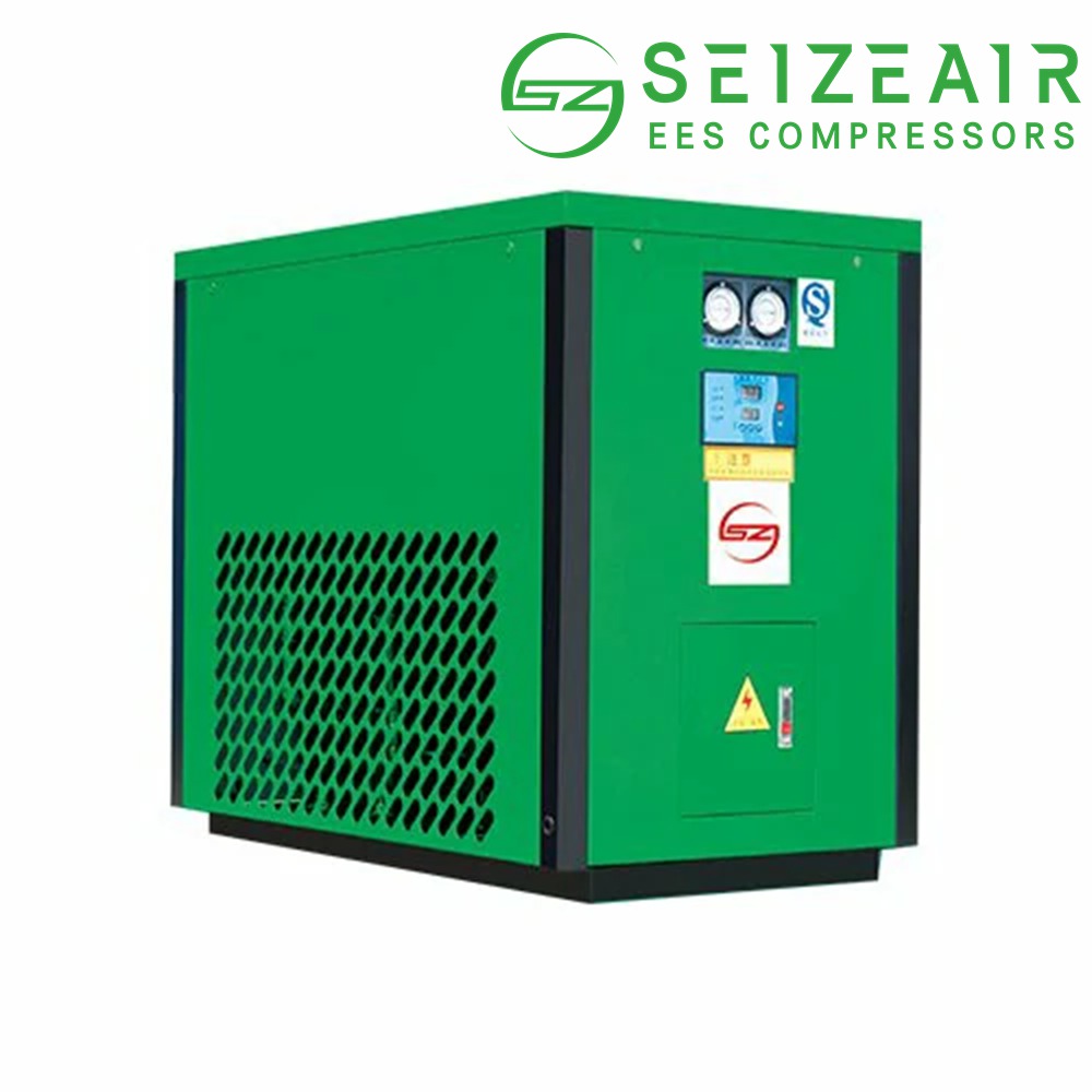
Two more things matter when you write the specification. The water number in your purity class applies at a defined sampling point rather than at the dryer outlet, so long distribution runs, ambient swings and pressure drop between the dryer and the tool all count. And desiccant dust is itself a particle source, which is why a dedicated after-filter downstream of every desiccant tower belongs in the base scope rather than in the options list. A properly specified desiccant air dryer therefore always ships with that after-filter included, while a precision filter at each branch takes care of whatever the pipework contributes afterwards.
Choosing the Right Compressor Technology for Electronics Manufacturing
Four technologies cover essentially every electronics duty, and the choice is decided mainly by flow range and by how much financial risk you assign to the possibility of hydrocarbon carryover.
| Technology | Typical flow range | Oil risk | Fit in electronics plants |
|---|---|---|---|
| Dry running oil-free screw | Roughly 10 to 120 m3/min | None from the air end; TUV Class 0 certified designs available | Central systems feeding SMT halls and cleanroom networks |
| Water-lubricated oil-free screw | Roughly 3 to 40 m3/min | None; treated water replaces oil inside the air end | Medium plants wanting Class 0 without high rotor temperatures |
| Oil-free scroll | About 0.2 to 2 m3/min per unit, banked for higher flows | None; very simple compression element | Labs, small lines, point of use packages, low noise areas |
| Oil-free centrifugal | Above roughly 60 m3/min | None from the air end | Large fabs with heavy, steady CDA demand |
For mid-size plants the discussion usually narrows to two options. A water-lubricated oil-free screw compressor puts treated water rather than oil inside the air end, which removes the hydrocarbon source and holds compression temperatures low, commonly below 60 C. Lower rotor temperature reduces thermal load on the aftercooler, reduces stress on internal coatings, and makes the machine noticeably easier to cool in a plant room during summer. The corresponding duty is water treatment discipline: conductivity control, periodic water changes and attention to seal condition.
Where flows are smaller, or where machines must sit close to production for space or redundancy reasons, an oil-free scroll compressor is a strong modular answer. There is no lubricant anywhere in the compression path, sound levels are low enough that machines can sit near production without an enclosure, and capacity can be added in small increments so you match growth instead of paying for a step change in capital years ahead of the demand.
Before sending enquiries to suppliers, working through a structured oil-free compressor selection guide will save weeks of clarification. Fix your purity class, worst case simultaneous demand, minimum acceptable pressure, compressor room ambient conditions, redundancy requirement and allowable sound level in one document, then ask suppliers to quote against it. This also makes the returned proposals genuinely comparable, which they usually are not when each vendor has silently assumed different figures.
Compressor Room Layout, Pipework and Cleanroom Compatibility
Air quality is largely decided by decisions that look like plumbing. Siting, intake routing, pipe material and drainage are unglamorous, but they determine whether the investment you made in the air end actually reaches the tool.
Siting and intake
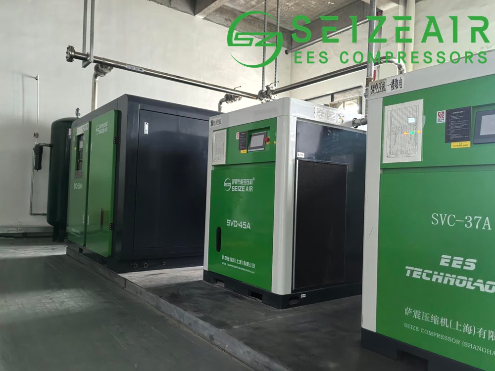
Put the intake on the cleanest available air and give the room real ventilation. Compressor rooms need enough air exchange so that radiator fan flow does not recirculate hot discharge air back into the intake, a failure that shows up every summer as unexplained trips and reduced output. Keep the room separate from any process generating solvents, dust or solvent vapour, and keep it physically separated from boiler or generator exhausts. If the plant has no clean external wall, ducting the intake to roof level usually costs less than the consequences of a contaminated one.
Ventilation and heat management
Rough rule of thumb: size room ventilation to remove the heat equivalent of the installed motor input minus heat carried away by any cooling system, then add margin for the hottest week of the year. Duct hot discharge air out of the building in summer and optionally back into the room in winter. Where the plant has space heating or process water to pre-heat, water cooled machines enable heat recovery that can return a large fraction of input energy.
Noise and vibration
Electronics plants often have the compressor room closer to people than heavy industry does, so structure borne vibration travels into adjacent production areas. Anti-vibration mounts, flexible connectors on discharge and cooling lines, and acoustic treatment of the room itself are usually cheaper when included in the original scope. Machines intended for near-line installation should be assessed for actual measured sound level at stated distance, not only for a catalogue figure.
Pipe material and ring main design
Use stainless steel or aluminium distribution rather than carbon steel, and design the ring main so air can reach any large consumer from two directions, keeping velocity moderate and pressure drop low. Slope the mains slightly in the direction of flow with automatic drains at every low point, take drops off the top of the header rather than the bottom, and avoid hard tees that leave dead pockets. Valved take-off points let you add capacity without shutting the plant down.
Drainage and condensate
Electronic zero-loss drains with alarm outputs should be fitted at the receiver, after each aftercooler, at every low point, and after each dryer. Route condensate to a separator before discharge and treat it where local rules require it. Alarm outputs are worth far more than the hardware cost, because a stuck-open drain can quietly consume a noticeable share of your compressed air production for weeks.
What ISO 14644 means for compressor equipment serving cleanrooms
ISO 14644 governs cleanroom classification, not compressed air quality, which is why the two get confused. Your compressor does not need to satisfy a cleanroom class, but the air it supplies must satisfy the purity class your process requires, and equipment located inside or adjacent to clean areas must not shed particles into the controlled environment. In practice that means smooth, cleanable external surfaces, no exposed fibrous insulation, sealed penetrations through cleanroom walls, and routine exterior cleaning with approved agents. Where a machine must sit inside clean-adjacent space, confirm enclosure ratings, material compatibility with cleaning agents, and the maintenance access route before ordering, because retrofitting access is painful.
What Does a Class 0 Air Compressor Really Cost to Own?
Purchase price is usually under a quarter of what a compressor costs across ten years; electricity is most of the rest. For electronics plants running two or three shifts this matters more than in most industries, because operating hours multiply every efficiency difference.
Annual electricity kWh = input power (kW) x operating hours per year Annual electricity cost = annual kWh x tariff Compare fairly with specific power: specific power = input power (kW) / delivered flow for example kW per 100 cfm, at identical discharge pressure and ambient conditions Ten-year ownership, roughly: purchase + installation + 10 years of energy + planned maintenance + filter elements + dryer energy + condensate handling – residual value Useful sensitivity checks: +1 bar discharge pressure ~ 6 to 7 percent more energy for the same mass flow leakage at 20 percent of production ~ one fifth of your air bill wasted VSD on a fluctuating duty cycle ~ typically 20 to 35 percent saving over fixed speed
Work the comparison in specific power per unit of delivered flow rather than in machine kW, because that immediately exposes differences hidden by nameplate claims. A machine that looks 3 percent more efficient but runs 0.5 bar higher than necessary loses that advantage completely, since raising discharge pressure by 1 bar costs roughly 6 to 7 percent more energy for the same output. In projects we have handled at Seize Air with electronics customers, rewriting that comparison has repeatedly changed the winning proposal.
Variable speed drive earns its keep here because electronics load profiles swing hard. Between shifts, during changeovers and at weekends demand collapses, and a fixed speed machine sitting loaded and blowing off pressure wastes energy every idle minute. In addition to the energy saving, VSD units hold a tighter pressure band, which is itself a yield benefit on high speed placement equipment.
Three other levers regularly get overlooked:
- Leakage. In plants older than five years it is common to lose 20 to 30 percent of produced air. Ultrasonic leak surveys cost little, and every leak fixed reduces the capacity you have to buy when production expands.
- Pressure reduction. Lowering distribution pressure cuts both energy and leakage flow at once. Many plants run higher pressure than any single tool requires simply because nobody has revisited the setpoint since commissioning.
- Heat recovery. Compressor heat can pre-heat process water, feed space heating, or support drying ovens. Counting that recovered heat changes the payback calculation materially.
A Worked Example
Suppose two proposals land on your desk for one SMT hall requiring 20 m3/min at 7.5 bar gauge, Class 2.2.1 at the point of use, running 6,000 hours a year at 0.10 per kWh.
Quote A is an oil-injected screw rated 110 kW with a three-stage filter train and a heatless adsorption dryer. Quote B is an oil-free screw rated 125 kW with adsorption drying. On purchase price A looks better. On electricity, A looks better again, because specific power is lower for lubricated compression, which is a genuine thermodynamic advantage of oil injection.
Illustrative annual energy, assuming both are correctly sized: Quote A 110 kW x 6,000 h = 660,000 kWh = 66,000 per year at 0.10 per kWh Quote B 125 kW x 6,000 h = 750,000 kWh = 75,000 per year at 0.10 per kWh Apparent energy gap in favour of A = 9,000 per year Now add what A does not include: filter element replacement every planned interval, plus labour oil and separator changes oil vapour / aerosol testing at least annually to evidence the oil class condensate treatment, assuming separator efficiency has not slipped estimated compressed air lost to dryer purge, similar for both contingency for one oil-related defect excursion Typical lifecycle picture once those lines are included: the energy gap narrows or reverses, and the risk line does not appear on any quotation but does appear on your warranty claims report
The point of the exercise is not that one technology always wins. It is that reading only the kilowatt figure makes Quote A look cheaper in a way that disappears once the whole lifecycle is written down. Plants that run this exercise before awarding also tend to find that the successful proposal changes depending on whether the ask is one machine, a hall, or a whole site with several halls and varying load.
Do the same arithmetic for dryers. A heatless adsorption dryer purging 15 percent of rated flow at full load on this duty is continuously consuming about 3 m3/min of finished air; over 6,000 hours that is not a rounding error, and it is why dew point dependent control and heated purge designs pay back on larger installations.
Certifications and Documentation Worth Requesting
Paperwork is tedious and it decides disputes. Ask for these items up front rather than after delivery, because retrospective documentation is rarely convincing.
- ISO 8573-1 compliance statement with the three classes named explicitly, not described qualitatively, together with the applicable parts of the standard used for testing.
- Independent Class 0 verification where Class 0 is specified, such as TUV testing to ISO 8573-2 for oil aerosol, with the report showing date, sampling point and conditions.
- Third-party type test reports for flow and specific power, so that quoted capacity is traceable rather than nominal.
- CE or EAC declaration of conformity and any local market certification needed at the installation country.
- Material certificates for wetted parts in the compressed air path, which matters when the air contacts product surfaces.
- Sound power and sound pressure measurements at stated distance, rather than a single unspecified decibel figure.
- Quality management certification such as ISO 9001 for the manufacturing plant, plus documented final test procedures.
- Factory acceptance test protocol agreed in advance, stating what will be measured and what counts as pass.
Where a machine will serve a cleanroom-adjacent space, add documentation for surface finish, enclosure ingress rating and cleaning agent compatibility. Where it will feed semiconductor tools, expect the tool manufacturer’s specification to override every generic recommendation in this article, and follow it.
Commissioning, Validation and Ongoing Monitoring
A specification holds value only if somebody verifies it. The pattern that works well in electronics plants is validation at three moments: at commissioning, after any major modification, and on a fixed annual schedule.
- Fit proper sampling ports at the agreed measurement points, typically compressor outlet, downstream of the dryer, and at representative points of use. ISO 8573-3 and ISO 8573-2 define acceptable sampling geometry, so install real ports rather than improvising off a drain valve, which distorts results badly.
- Test each of the three classes with the right instrument: a condensation particle counter or equivalent for particles, a calibrated dew point meter with adequate range for water, and validated sampling tubes or a correctly configured analyser for oil vapour.
- Log differential pressure across every filter housing during routine rounds. The trend tells you when to change elements and how much energy a change will recover.
- Record dew point continuously rather than periodically. Trending catches dryer degradation before it becomes a class failure and gives you clean evidence during a customer audit.
- Keep a contamination control file. Certificates, test reports, filter change records and element batch numbers together make up exactly the documentation auditors ask for, and they take minutes to keep up to date compared with days to reconstruct.
Monitoring is where quiet value lives. Most modern controllers expose flow, power, pressure, dew point and differential pressures over standard industrial protocols, and alarming on deviations rather than failures lets teams intervene during a planned window rather than during production. Plants that instrument well tend to discover the same unglamorous truth: consumption drifts upward slowly for months before anyone notices, and that trend is almost always leakage or a valve someone left open.
Mistakes Buyers Make When Specifying Electronics Grade Compressed Air
- Comparing machines on price per kW across technologies. An oil-injected unit with additional filtration and a genuinely oil-free unit are not the same product, and kilowatts alone hide that.
- Writing “oil-free” without a class or a test method. Without a number and a standard, nothing in the claim is enforceable.
- Locating the intake where it costs least instead of where the air is cleanest. That one decision shapes your baseline for fifteen years.
- Sizing the dryer to the compressor rather than to worst case. Dryers must be rated for maximum flow at maximum inlet temperature, not nominal average.
- Specifying carbon steel distribution and expecting clean outlets. Pipe material is effectively permanent.
- Putting everything into one large machine. Redundancy and turndown are usually worth more than the small capital saving.
- Forgetting that dryers and filters are also single points of failure. N+1 thinking has to extend past the compressors.
- Treating commissioning reports as a one-time deliverable. Air quality drifts; verification has to be periodic to mean anything.
- Ignoring floor loading, access routes and lifting height. Plenty of otherwise fine projects have been delayed because a replacement air end could not physically be removed.
Frequently Asked Questions
Is an oil-free air compressor enough on its own for electronics manufacturing?
No. It removes oil added by the machine, not hydrocarbons already in ambient intake air nor water and particles picked up in the distribution system. For a Class 1 or better result at the point of use you still need properly sized drying and filtration, clean pipework, sensible siting and periodic verification.
Which ISO 8573-1 class should an SMT line specify?
A defensible starting point for most assembly operations is 2.2.1: particle Class 2, pressure dew point -40 C, oil Class 1. Step up to particle Class 1 wherever air touches solder paste, conformal coating or optical surfaces, and follow the tool manufacturer’s specification for semiconductor or display processes.
Can water-lubricated screws genuinely be called oil-free?
Yes, when the design places no hydrocarbon in the compression path. Treated water replaces oil entirely, which is why these machines are used where Class 0 air is needed without the high rotor temperatures of a dry screw. The trade-off is the discipline required in water treatment and conductivity control.
How often should air purity be tested in an electronics plant?
A reasonable baseline is annual testing for all three classes with continuous dew point logging, plus an unscheduled check whenever a process changes or a board defect pattern appears. Plants supplying automotive or medical electronics customers often move to six-monthly intervals to satisfy audit expectations.
Why is dew point worse at the point of use than at the dryer outlet?
Pressure drop, pipe cooling and desorption from internal surfaces all contribute. Pressure dew point improves as pressure falls, but the safety margin you need comes from selecting a dryer one class better than the specification strictly demands, and from keeping pipework and drains genuinely dry.
Does a smaller scroll package make sense alongside a central system?
Often yes. Dedicated local machines serving one sensitive process or a laboratory give independence from plant-wide trips and let you hold tighter local air quality, and their low sound output means they can sit near production without an enclosure.
How much does VSD actually save in an electronics plant?
On a fluctuating duty cycle, commonly 20 to 35 percent against a fixed speed equivalent, sometimes more on plants with heavy weekend or shift variation. The secondary benefit, a tighter pressure band, is harder to quantify and often more valuable in yield terms.
What information should go into an enquiry for an electronics-grade system?
Purity class required per process, worst case simultaneous flow, minimum acceptable pressure, ambient conditions at the compressor room, redundancy philosophy, available utilities, allowable sound level, and any local certification requirements such as CE, EAC or TUV Class 0 verification.
Talk to Our Compressed Air Specialists
If you are specifying, upgrading or troubleshooting an air compressor for electronics industry duty, the fastest route to a dependable answer is to review your actual load profile alongside your weakest purity point. Send us your flow and pressure data, your process list and any air quality measurements you already hold, and we will come back with a configuration proposal including an energy comparison and payback estimate. Start a compressed air audit today and speak to Seize Air specialists who build oil-free compressor systems around measured purity rather than catalogue claims.