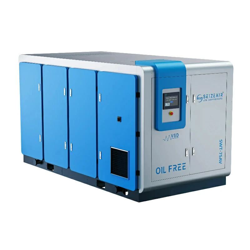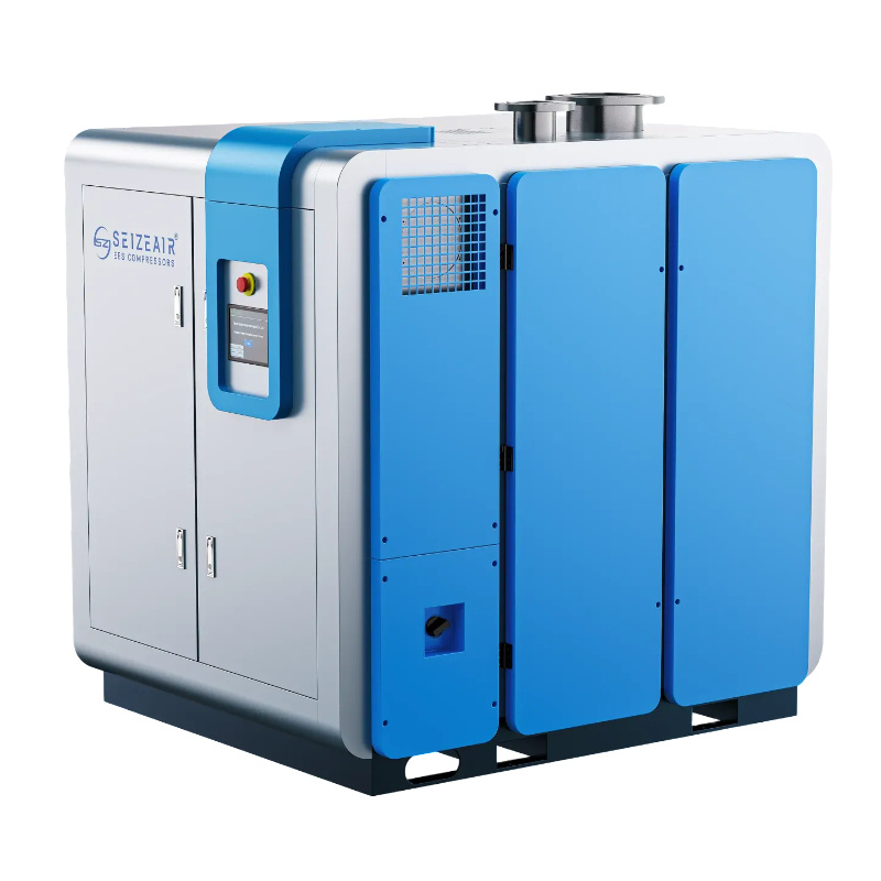


Centrifugal blower selection decides how much of a plant’s electricity disappears into aeration, conveying or oxidation air, and most buyers discover the mistake only after commissioning. This guide explains how a centrifugal blower generates flow and pressure, how to read its performance curve, how to size one against real site conditions, and which mechanical choices, bearings, impeller, drive and cooling, still matter a decade later. It is written for engineers, maintenance managers and procurement teams who have to defend a decision, not simply place an order.
The information below is drawn from SEIZE AIR’s own published blower data (Magnetic Levitation Blower catalogue, version 2025-10) and from general fan and compressor engineering practice. Where a number belongs to a specific model, the model is named; where a number depends on the site itself, the calculation method is given instead of an invented figure.
What a Centrifugal Blower Actually Does
A centrifugal blower accelerates air with a spinning impeller and then converts most of that velocity into static pressure inside a diffuser and volute. Air enters at the impeller eye, travels outward between the blades, leaves the tip at high speed and slows down in the expanding casing. Delivery is continuous rather than pulsating, and that single property explains most of the technology’s advantages in large air duties.
How the impeller moves air
Blade geometry sets the personality of the machine. Backward-curved blades, bent away from the direction of rotation, hold pressure over a wide flow range and lose it gently as demand rises. Radial blades push harder at the same tip speed but demand more power. Forward-curved blades move large volumes at modest pressure and become unstable near their limit.
SEIZE AIR builds its PC series around a backward-curved, three-level flow impeller machined as a single piece on a five-axis machining centre. The material is an aviation-grade aluminium alloy chosen for stiffness against deformation, the surface is anodised for corrosion and wear resistance, and every impeller is spun to 115% of design speed before it is released. Tip speed, not nameplate power, is the real ceiling on pressure: pressure rise climbs roughly with the square of tip speed, so a compact impeller running fast can match a much larger slow-turning one.
Where the pressure comes from
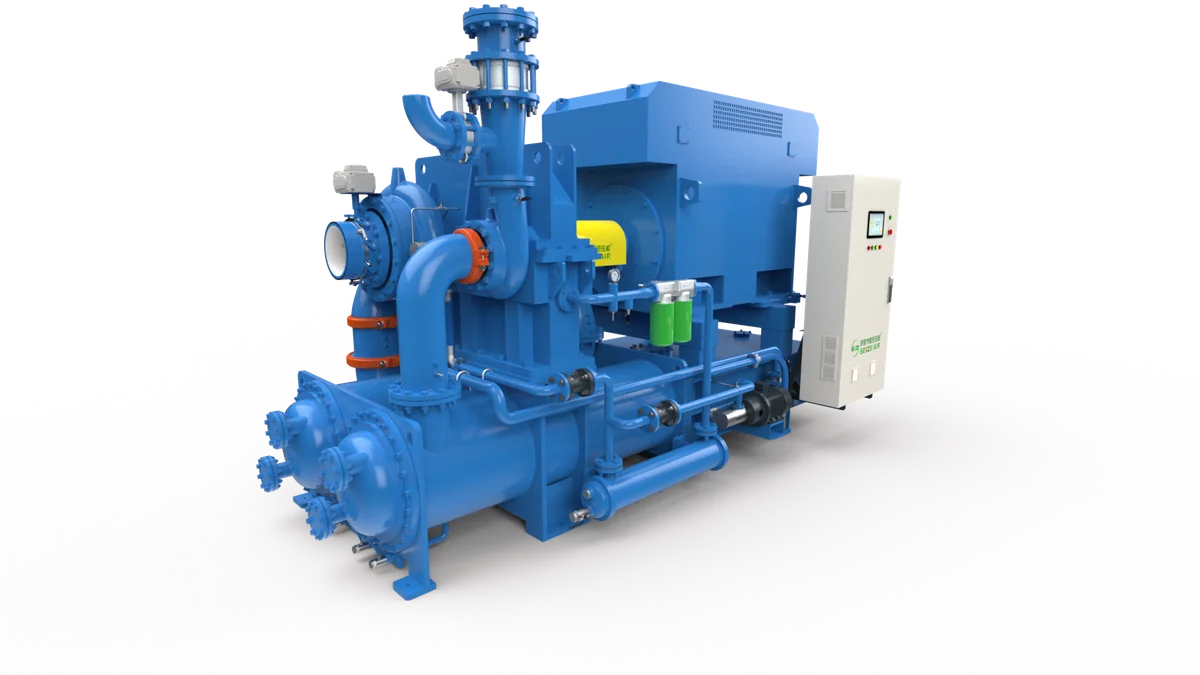
Static pressure is generated twice. Centrifugal action inside the impeller passages does the first part; deceleration in the diffuser and volute does the second. One stage comfortably covers the low-pressure band, which is the band the PC series occupies, from 30 kPa to 120 kPa working pressure. Duties above that band normally move to a gear-driven machine such as the SC series centrifugal air compressor, which shares the aerodynamic principle but not the bearing system, the casing or the price.
Two loss mechanisms dominate day-to-day behaviour: incidence loss when air meets the blade at the wrong angle, and friction and diffusion loss inside the flow passages. Both grow as operation drifts away from the design point. That is why an identical casing can look excellent on a data sheet and disappointing in service, and why the duty point matters more than the headline efficiency.
Blower, fan or compressor: the useful dividing line
Industry usage of these words is not perfectly consistent, but the practical boundary is pressure rise. Fans move air with a negligible density change. Inside the blower band the gas still behaves almost incompressibly, yet the discharge must overcome real system resistance. Compressors cover duties where density change can no longer be ignored and the machine is designed around compression ratio rather than volume movement.
Getting the category right at the enquiry stage prevents two expensive errors. The first is specifying a fan for a duty that needs blower pressure, which ends with a machine running at the end of its curve and never reaching design flow. The second is buying compressor hardware for a blower duty, which pays for pressure capability that the process will never use.
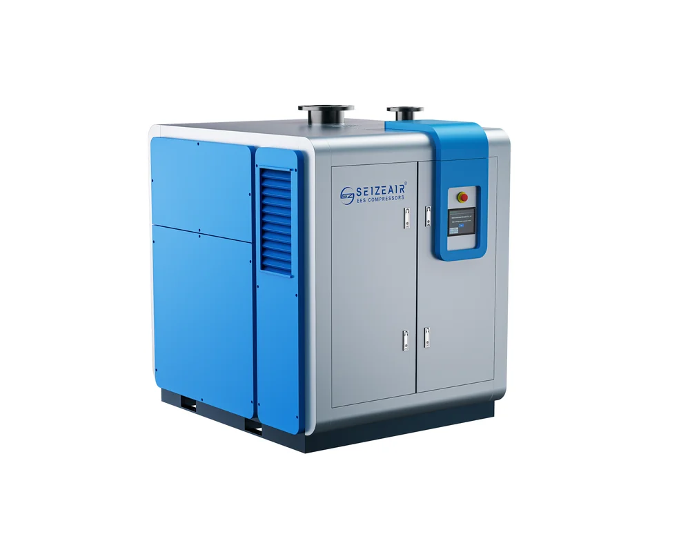
Centrifugal Blower vs Roots Blower vs Screw Blower
Three technologies dominate low-pressure process air. Each one wins inside a particular band, and the differences show up in operating cost rather than purchase price.
| Property | Rotary lobe (Roots) | Screw blower | Centrifugal blower |
|---|---|---|---|
| Working principle | Positive displacement, no internal compression | Positive displacement with internal compression | Dynamic, velocity to pressure |
| Delivery | Pulsating, volume fixed by speed | Smooth, volume set by rotor speed | Continuous, volume set by curve position |
| Typical pressure band | Low, single stage | Low to medium, up to about 2 bar | Low, roughly 0.3 to 1.2 bar |
| Part-load behaviour | Poor without speed control or blow-off | Good with variable speed | Excellent with variable speed, wide turndown |
| Oil in the air path | Usually none, but lubricated bearings and gears | Oil-free versions available with oil-free rotors | None: magnetic bearings carry the shaft |
| Wear parts | Lobes, seals, gears, belts | Rotors, seals, gears, oil system | Bearings are contact-free; filters and cooler dominate |
| Best fit | Small to medium duties, abrasive or dirty gas | Medium duties needing pressure flexibility | Large air volumes at low pressure |
Roots blowers: simple, but the losses are built in
Rotary lobe machines trap a fixed volume and push it into the discharge line without compressing it internally. The pressure has to rise somewhere, so it rises abruptly at the port, and that equalisation step shows up as heat and noise rather than useful work. Mechanical simplicity keeps the purchase price low and the repair procedure familiar.
Efficiency falls away quickly at part load because volume is tied to shaft speed. Plants usually compensate with a blow-off valve or a variable frequency drive; the first wastes air that has already been paid for, the second helps but cannot recover the port losses.
Screw blowers: displacement with internal compression
A screw blower closes the inlet port, reduces the trapped volume before opening to discharge, and therefore reaches line pressure with far less equalisation loss. SEIZE AIR’s SPVC series oil-free screw blower uses a 3 x 5 spiral screw rotor profile, a permanent magnet motor with independent air cooling, and a speed range from 60% to 100%, quoted to ISO 1217 Annex C. Working pressure spans 0.4 to 2.0 bar across the range, which is wider than the PC centrifugal band.
Centrifugal blowers: continuous flow, strongest at scale
Because a centrifugal stage has no rubbing contact in the air path and no fixed geometric displacement, it scales well. Large volumes arrive in a compact footprint, and variable speed gives a broad, stable operating window. The SEIZE AIR magnetic levitation centrifugal blower spans 22 kW to 400 kW and reaches 400 m³/min at 40 kPa on the largest frame.
Two constraints come with the principle. A centrifugal stage cannot deliver high pressure without either more stages or very high tip speed. It also has a surge limit on the low-flow side, so the control system must protect the machine when demand collapses.
Reading a Centrifugal Blower Performance Curve
A blower data sheet is a family of curves, not a single rating. Flow, pressure and power are linked, and the link changes with speed, inlet density and temperature. Buying from the headline number alone is the most common cause of a machine that runs but never delivers.
The lines on every curve
Four lines carry the useful information. Pressure plotted against flow shows what the stage can produce at a given speed. Shaft power, drawn on the same axis, usually rises as flow increases at constant speed. The efficiency island marks where the stage converts energy best, and the surge line marks the minimum stable flow.
Design point sits inside the efficiency island, not at its edge. A duty chosen on the far right of the curve may need a larger motor than expected and will run hot on power. A duty chosen close to the left wall will be efficient on paper and unstable in practice.
Surge and the left-hand wall
When system resistance rises far enough, flow falls below the value the impeller can sustain and the flow reverses briefly. Pressure spikes, the shaft thrusts axially, and the cycle repeats. The mechanical damage comes from repetition, not from a single event.
Magnetic bearings make surge protection more, not less, important. Their controller can react within milliseconds, but the axial bearing carries the full thrust excursion, and repeated excursions consume the protective bearing clearance. Reliable packages combine a minimum-flow limit in the controller, a fast-acting blow-off or bypass valve, and a speed ramp that never allows the operating point to drift left of the surge line.
Correcting for altitude, temperature and humidity
Published capacity is normally stated at a reference condition. SEIZE AIR quotes PC series capacity at 1 atm and 20 °C, and the SPVC screw blower range is quoted at 1 bar and 20 °C, with an altitude limit of 1000 m and an ambient range of -20 °C to 45 °C. Move the machine to 1500 m, or feed it 45 °C air, and the mass of air moved per revolution falls, even though the volume reading at the inlet looks unchanged.
Process requirements are usually written in mass or in standard volume, so convert before you compare quotations. Two suppliers quoting volume at different reference conditions can appear to differ by more than 10% when their machines are physically identical in capability. Ask for the correction basis in writing.
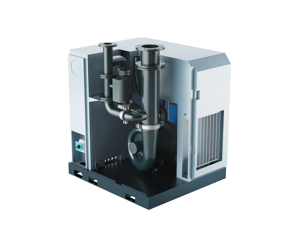
Sizing a Centrifugal Blower in Six Steps
Sizing is a sequence of narrowing decisions. Skipping a step usually transfers the uncertainty to the commissioning team, where it is far more expensive to resolve.
Step 1: define the duty as mass flow
Start from the process requirement: oxygen demand in a basin, conveying rate in a pipeline, air change rate in a tank. Convert to mass flow using the actual inlet temperature, barometric pressure and humidity at the site. Volume flow then follows from density, and only at that point does it make sense to compare against a published curve.
Step 2: add the real system resistance
Sum every element between the blower discharge and the point of use: pipe friction, fittings, valves, silencers, diffusers, static head in a submerged aeration system, and the fouling allowance for headers and diffusers that will accumulate over a service interval. Add the inlet side too, because a clogged filter costs pressure before the air ever reaches the impeller.
Design margin should be a deliberate number, written down and justified, not a habit. A small allowance covers normal fouling; a large one pushes the operating point to the right of the curve, where power consumption rises and the motor may be undersized for the actual duty.
Step 3: check the operating band, not just the point
Plot the maximum and minimum demand on the same curve at minimum and maximum speed. Both extremes must sit inside the stable region, with margin to surge on the left and margin to motor limit on the right. Seasonal load swings, night-time turndown and blocked-filter conditions all belong on that plot.
Step 4: choose the drive and the control concept
Fixed speed plus a throttle valve is cheap to buy and expensive to run. Variable speed follows demand directly and usually pays back fastest where the load profile spends real hours below maximum. For multi-basin plants, a coordinated group with one trimming machine often beats several independently controlled units.
Step 5: confirm utilities and environment
Check the cooling medium, available pressure and quality, ambient temperature in the enclosure room, altitude, dust load, corrosive gases and the electrical supply. A blower rated for 45 °C ambient behaves differently inside a 50 °C compressor room with recirculating hot air, and no amount of controller tuning fixes a cooling shortfall.
Step 6: write the specification around the duty
State the mass flow, the pressure at the discharge flange, the reference condition, the turndown required, the acceptable noise level at a stated distance, the cooling medium, the control interface and the documentation expected. A specification written this way is comparable across suppliers; a specification that lists only kilowatts is not.
What the PC Series Data Sheet Tells You
Concrete numbers make the selection logic easier to follow. The PC series is published as nineteen models from 22 kW to 400 kW, with capacity tabulated at ten working pressures between 30 kPa and 120 kPa. Reading across a row shows how flow falls as pressure rises on the same frame; reading down a column shows how much flow a larger motor buys at one pressure.
| Model | Motor power (kW) | Capacity at 40 kPa (m³/min) | Capacity at 80 kPa (m³/min) | Capacity at 120 kPa (m³/min) | Outlet (DN) |
|---|---|---|---|---|---|
| PC22 | 22 | 29 | 15 | — | 200 |
| PC37 | 37 | 49 | 26 | — | 200 |
| PC55 | 55 | 69 | 38 | — | 200 |
| PC90 | 90 | 113 | 62 | 46 | 200 |
| PC160 | 160 | 205 | 112 | 81 | 200 |
| PC250 | 250 | 320 | 175 | 126 | 300 |
| PC315 | 315 | 400 | 221 | 159 | 400 |
| PC400 | 400 | — | 281 | 202 | 400 |
Reading the model code and the blanks
The number in the model code is the motor power, so PC90 is a 90 kW machine. Blank cells are as informative as filled ones: they show where a frame is not offered at a given pressure, which prevents the common mistake of assuming that every model covers the full pressure range.
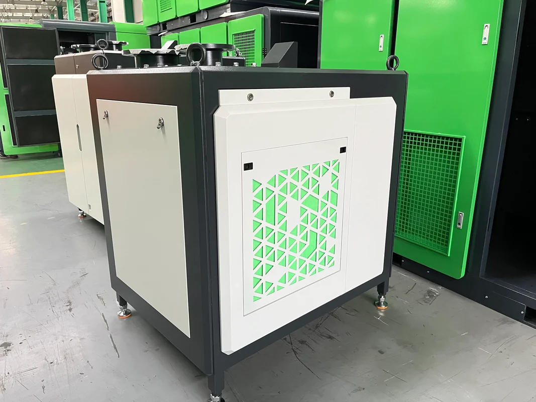
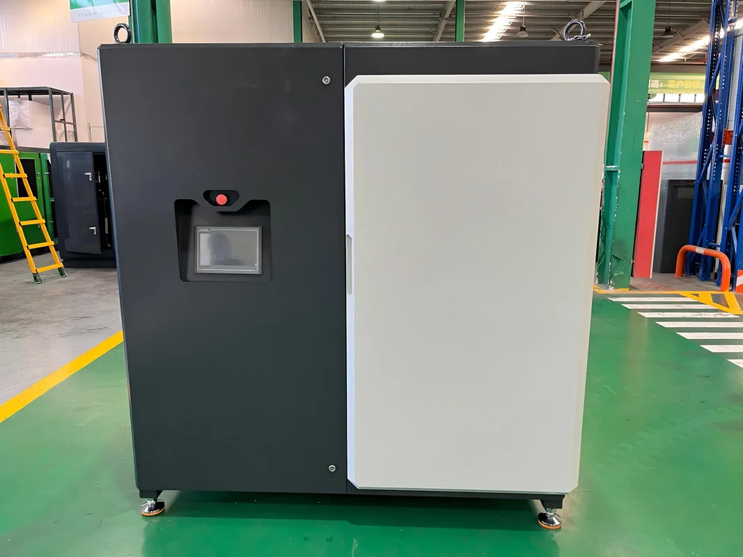
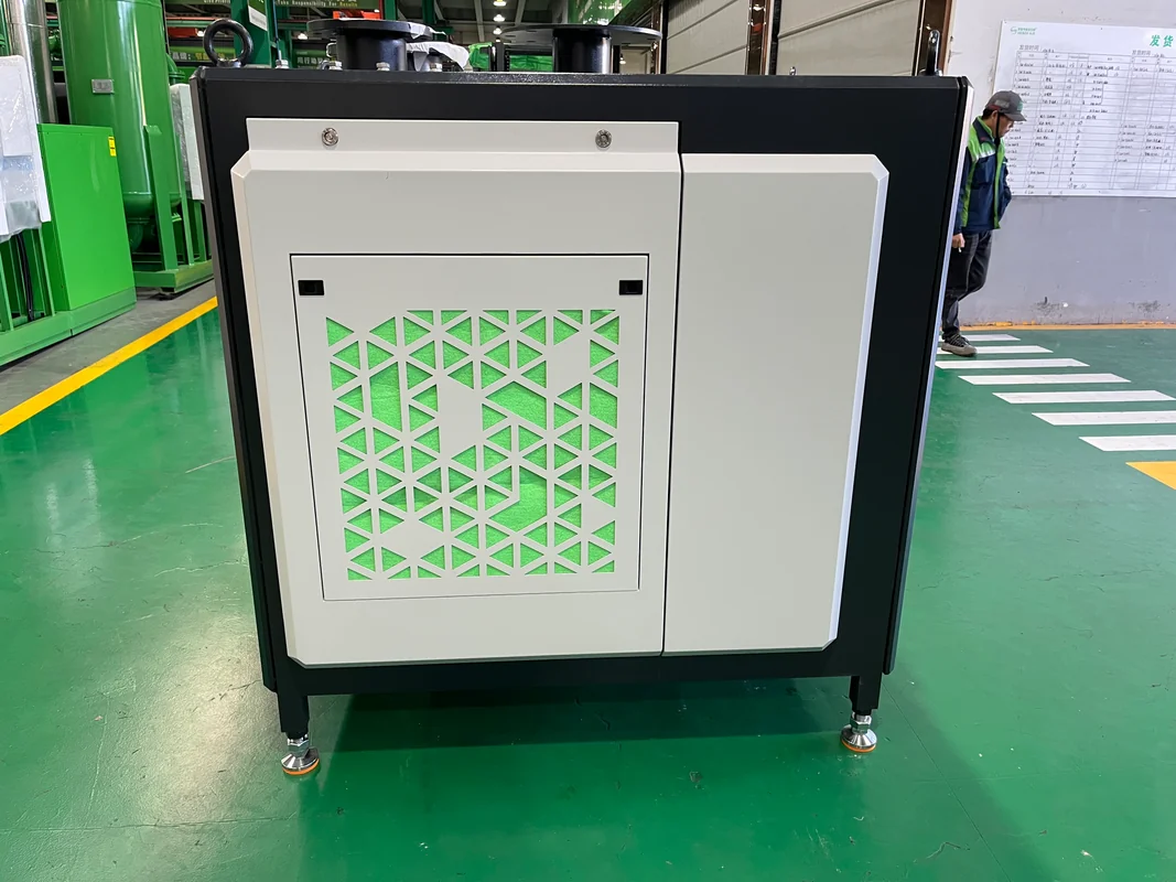
Frame sizes also step in geometry. Units from PC22 to PC90 share a 1750 x 1250 x 1200 mm envelope and a DN200 outlet, with weights of 700 kg. From PC110 the frame grows to 1900 x 1450 x 1300 mm, and the largest frames reach 2500 x 2000 x 2100 mm and 1800 kg with a DN400 outlet. Those dimensions decide whether a unit fits through an existing doorway, which is a project constraint long before it becomes an engineering one.
Bearings: Why Magnetic Levitation Changes the Maintenance Story
Bearings are where a high-speed blower either earns its reputation or loses it. Rolling elements need lubrication, gears need oil, and both impose a service routine that never stops. Active magnetic levitation removes contact entirely, and that single change rewrites the maintenance calendar.
How active magnetic bearings hold the shaft
The PC series floats the rotor on two radial magnetic bearings and one axial thrust bearing, giving five axes of active control. Position sensors report the shaft location to the controller, which corrects the coil current roughly ten thousand times per second. Because nothing touches, there is no lubricant in the bearing, no seal to weep and no friction loss to cool.
SEIZE AIR rates the bearing actuators to IP67 and designs them for a twenty-year service life. The rotor itself runs inside a thermally controlled motor assembly with air cooling for the windings and liquid cooling for the housing, which keeps the air gap stable when the plant gets hot.
What happens when the power fails
A magnetic bearing needs electricity to exist. The package answers that with self-generation: when the supply drops, the inverter switches the motor into generating mode and the rotor’s own inertia supplies the control system and bearings until the shaft coasts to a stop. Protective bearings then catch the rotor if it lands.
Those protective bearings are tested to survive thirty impeller-drop events, which is the design case rather than an operating allowance. An optional single-phase input, three-phase output UPS extends the ride-through window further for plants with unstable grids.
What disappears from the routine
Oil changes, oil analysis, oil filters, seal replacement and gearbox inspection leave the schedule. What remains is still real work: intake filters, cooler condition, sensor calibration checks, controller battery and event-log review. The trade is favourable because the remaining tasks are inspections that can be planned, not consumables that must be bought on a cycle.
Motor, Drive and Control
The aerodynamic side sets what the machine can do; the electrical side decides how closely it follows demand. Most of the recoverable energy in a blower installation sits in this second half.
Direct drive with a permanent magnet rotor
The impeller mounts on the motor shaft, so there is no belt, no coupling and no gearbox between the drive and the air. Each of those removed components was a loss point and a maintenance item. Permanent magnet rotors with samarium-cobalt magnets keep their strength at elevated temperature, and the integrated design lets the controller treat motor and impeller as one machine.
Variable speed as the primary control
Speed control matches output to demand instead of throttling it away. On a centrifugal stage the relationship is favourable: reducing speed reduces both flow and pressure, and the absorbed power falls faster than either. The practical benefit depends entirely on the load profile, so measure the profile before promising a saving.
Pressure control is normally closed-loop on the discharge header, with the setpoint chosen slightly above the highest consumer rather than at the blower outlet. Every unnecessary pascal in that setpoint is paid for continuously.
Group control and remote monitoring
SEIZE AIR packages the blower as part of an intelligent air station: Modbus links inside the plant, 4G, Wi-Fi or Ethernet outward, LoRa wireless for dispersed equipment, and a software layer that records twenty-four-hour trends, fault alarms, historic data and remote start-stop. Sequencing several machines under one controller lets the group run close to its combined best-efficiency line and keeps one unit as trim rather than cycling all of them.
Installation and Piping Decisions That Decide Performance
A correct selection can still underperform if the installation fights it. The failures are predictable, and all of them are cheaper to prevent than to correct.
Inlet filtration and inlet location
The PC series uses a three-level filtering system at the intake, and the arrangement matters as much as the filter grade. Duct the inlet to clean, cool air outside the plant room where possible. A short, straight inlet run helps; a tight elbow immediately before the filter housing creates a biased flow that loads one part of the element and lets dust past the rest.
Inlet temperature is a direct cost multiplier. Air drawn from a hot roof space is less dense, so the machine must run faster to move the same mass. Every degree of avoidable inlet heat is paid for on every operating hour.
Discharge piping, silencers and expansion joints
Size discharge pipe for velocity, not for convenience. Oversized pipe costs money; undersized pipe costs pressure continuously and adds noise. Support the pipe independently of the blower, and fit an expansion joint so that thermal growth and casing vibration do not load the outlet flange.
Silencing belongs on both sides. SEIZE AIR offers a customised silencer with an internal silencing mesh surrounded by acoustic material, quoted as reducing noise by an average of 2 dB beyond the standard arrangement, and the inlet filter housing also carries acoustic treatment. Where the blower sits close to a boundary, treat the room as part of the acoustic design.
Cooling water and heat recovery
The PC series uses an integrated low-pressure water cooler with a built-in moisture separation filter screen. Water flows inside the tubes and air passes outside them, with aluminium fins to raise heat exchange efficiency; condensing in the intercooler pulls the compression path closer to isothermal, which is where the efficiency comes from.
Because the heat leaves in water rather than air, it can be recovered. Basin heating, wash-water preheating and space heating are all realistic uses for a continuous low-grade stream, and the return on that investment is often better than the return on a more efficient motor.
Foundations, clearance and lifting
The package needs a flat, level base able to carry the wet weight plus pipe loads, with drainage for condensate. Leave the service clearances stated in the manual, particularly at the filter and cooler access panels, and check the lifting points against the certified weight on the nameplate. Where space is genuinely tight, a containerised air compressor station moves the integration problem into a factory-built enclosure.
How to Calculate Energy Cost Without Guessing
Blower economics live almost entirely in the electricity bill, so the calculation deserves to be explicit rather than asserted. Two rules keep it honest: use measured or specified shaft power at the actual operating point, and use hours that reflect the real load profile.
The calculation, step by step
Annual energy equals absorbed power in kilowatts multiplied by operating hours per year, adjusted for motor and drive efficiency, multiplied by the tariff. Absorbed power comes from the blower curve at the duty flow and pressure, corrected for inlet density. Tariff comes from your own utility contract, and reference electricity price data is published by bodies such as the U.S. Energy Information Administration.
Run the calculation three times: at design flow, at the average flow the plant actually needs, and at the minimum night-time flow. The average case is the one that pays the bills, and it is the one most often omitted from a quotation comparison.
Why part-load behaviour dominates
A blower sized for peak demand spends most of its life away from peak. If the control strategy cannot follow demand down, the machine either runs at full power and blows off excess air or throttles against a valve. Both convert paid electricity into noise and heat.
This is also where the technology choice shows up. A positive displacement machine loses part-load efficiency quickly unless speed control is fitted; a centrifugal stage with variable speed keeps a usable efficiency band over a wide flow range. Compare the machines at your load profile, not at their rated points.
Maintenance Plan for a Centrifugal Blower
The absence of an oil system simplifies the schedule without emptying it. What remains is filter care, cooling performance, sensor integrity and record keeping. A short, disciplined routine prevents nearly all unplanned stops.
| Interval | Task | Reason |
|---|---|---|
| Daily | Check discharge pressure and current against baseline | Early warning of fouling or surge |
| Weekly | Inspect intake filter differential, drain condensate | Protects impeller and cooler |
| Monthly | Review event log, verify sensor readings, check cooling water flow and temperature | Catches drift before it becomes a trip |
| Quarterly | Clean cooler, verify blow-off or bypass valve operation | Restores heat exchange and surge protection |
| Annually | Bearing controller diagnostics, protective bearing inspection, impeller and casing inspection, sensor calibration | Confirms the levitation system is healthy |
What the trend tells you before the alarm does
Record discharge pressure, motor current, speed and temperatures at a fixed reference condition once a week. A slow rise in current at constant flow points to fouling on the impeller or cooler. A slow drop in achievable pressure at constant speed points to intake restriction or internal leakage. Both are visible weeks before a trip.
Spares and support
Hold intake filter elements, a cooler service kit, sensor spares and controller batteries. Larger items are usually better covered by a service agreement than by inventory. SEIZE AIR publishes a service footprint across Europe, Asia, Africa, Latin America and Oceania, and the company profile sets out its manufacturing base in Shanghai’s Jiading High-Tech Zone.
Applications: Where a Centrifugal Blower Earns Its Place
Low-pressure air at high volume appears in more processes than most plant teams realise. The common thread is a continuous demand that never quite matches a fixed machine rating.
Wastewater aeration
Aeration is usually the largest single electrical load at a municipal or industrial treatment plant, and the demand follows diurnal and seasonal loading. Diffuser depth sets the pressure, basin volume sets the flow, and dissolved oxygen control sets the turndown requirement. Because the load profile is genuinely variable, a variable-speed centrifugal blower with a wide stable band fits the duty better than a fixed-speed displacement machine. Industry guidance on aeration practice is published by the Water Environment Federation.
Aquaculture and intensive fish farming
Dissolved oxygen is the limiting factor in high-density tanks and ponds, and the consequence of a blower stop is measured in stock rather than in schedule. Redundancy, fast restart and clean inlet air matter more than a fraction of a percent of efficiency, and the enclosure design should assume a humid, saline atmosphere.
Pneumatic conveying of powders and ash
Dilute-phase conveying needs a steady volume at modest pressure, and pulsation shows up as blockage. Continuous centrifugal delivery suits long runs with multiple pick-up points, provided the system resistance is calculated for the worst-case line and the control system protects against the surge that follows a closed valve.
Galvanizing, plating and chemical oxidation
Agitation, sparging and oxidation tanks need oil-free air, because oil in the bath contaminates the process rather than the product. Magnetic bearings put no lubricant anywhere near the air path, which removes a contamination route that no downstream filter fully closes. Where the process also needs higher pressure for a separate duty, an oil-free screw air compressor covers it without introducing oil into the building.
Flotation and process air
Dissolved and induced air flotation depend on bubble size and distribution, which depend in turn on stable pressure at the distributor. A blower with a flat pressure characteristic near the duty point holds bubble size far more consistently than one operating on a steep part of its curve. Where the plant also needs clean, dry instrument air, a post-processing train handles drying and filtration separately from the process air supply.
Procurement Checklist
Send the following with any enquiry. Suppliers who receive it give comparable answers, and the ones who cannot answer it are telling you something useful.
- Process duty in mass flow, with the reference condition stated
- Required discharge pressure at the blower flange, plus calculated system resistance
- Minimum and maximum demand, and the hours spent at each
- Site altitude, ambient temperature range and inlet air source
- Cooling medium, available flow, pressure and temperature
- Electrical supply, control voltage and preferred communication protocol
- Noise limit, stated as a level and a distance
- Redundancy and turndown expectations
- Documentation required: curves at actual speed, test standard, drawings, spare parts list
- Acceptance criteria and the test standard to be used
Common Mistakes
Most disappointing blower installations repeat one of five errors. Each is avoidable at the specification stage.
- Selecting on volume without density correction. A machine chosen at 20 °C and sea level under-delivers on a hot site at altitude.
- Ignoring the minimum-flow limit. Surge protection is a design requirement, not an optional extra.
- Undersizing the discharge main. Pipe velocity costs pressure every hour of every day.
- Fitting a large motor to cover uncertainty. The extra capability is paid for whether or not it is used, and the operating point moves off the efficiency island.
- Treating the room as an afterthought. Inlet temperature, cooling water and hot-air recirculation decide whether the machine meets its rating.
Frequently Asked Questions
What pressure range does a centrifugal blower cover?
The SEIZE AIR PC series is published from 30 kPa to 120 kPa working pressure, which is 0.3 to 1.2 bar. Above that band, a gear-driven centrifugal compressor or a two-stage machine is the appropriate choice.
How much flow can one unit deliver?
On the largest published frame, PC315 delivers 400 m³/min at 40 kPa. Flow falls as pressure rises on the same frame: PC315 moves 221 m³/min at 80 kPa and 159 m³/min at 120 kPa.
Is a centrifugal blower oil-free?
The compression path is oil-free because the shaft is carried on active magnetic bearings rather than lubricated rolling elements, and the motor is integrated on the same shaft without a gearbox. There is no oil reservoir in the package.
What happens to the bearings during a power cut?
The motor switches to generating mode and uses the rotor’s inertia to keep the levitation controller energised until the shaft stops. Protective bearings catch the rotor at the end of the coast-down, and the package can be supplied with a UPS for longer ride-through.
Can it run at low demand without surging?
Yes, within the stable band shown on the curve. Below the surge line the controller must either reduce speed or open a bypass. The correct approach is to plot the real minimum demand on the curve during selection rather than relying on a turndown percentage.
How is capacity verified?
Ask for the test standard and the reference condition on the data sheet. SEIZE AIR quotes PC capacity at 1 atm and 20 °C, and quotes the SPVC screw blower range to ISO 1217 Annex C at 1 bar and 20 °C. Comparing figures quoted on different bases is the most common source of apparent disagreement between suppliers.
What maintenance does a magnetic bearing blower need?
Filter replacement, cooler cleaning, sensor verification, event-log review and periodic bearing controller diagnostics. There is no oil change, no oil analysis and no gearbox inspection, because neither oil nor gears are present.
Can several units work together?
Yes. Group control with Modbus, Ethernet or wireless links lets a station sequence machines, appoint a trim unit and hold header pressure with fewer starts. This is the configuration SEIZE AIR describes as an intelligent air station, and it usually beats oversizing a single machine.
Choosing With Evidence, Not Habit
A centrifugal blower is a simple machine in principle and a demanding one in application. The stage is efficient only near its design point, the curve is only meaningful at a stated density, and the control strategy decides the bill more than the nameplate efficiency does. Get those three right and the rest of the specification follows.
Start from mass flow, plot the real operating band, confirm the utilities, and calculate energy at average load rather than at peak. Where the duty needs higher pressure than a single stage can reach, say so and move to a different machine instead of stretching the wrong one. Our engineers can review a duty with you and return curves at your actual conditions; the contact page is the fastest route in.