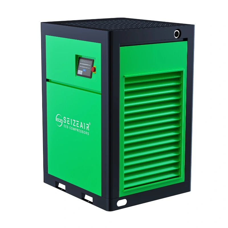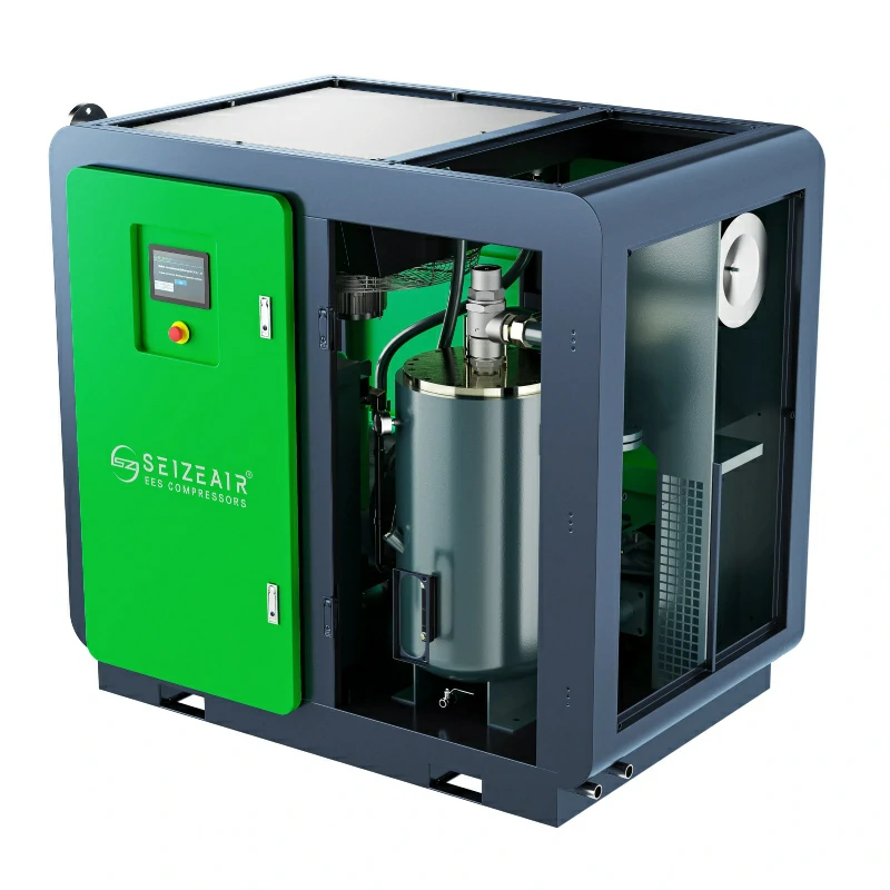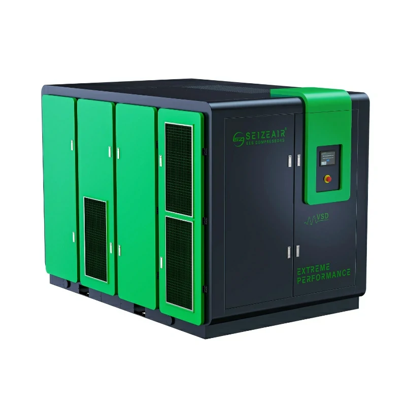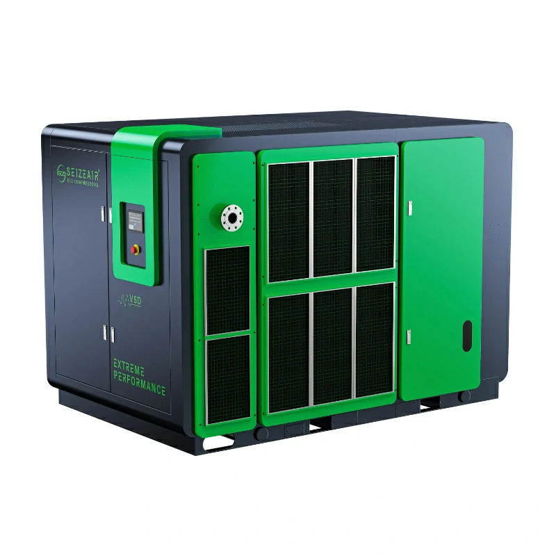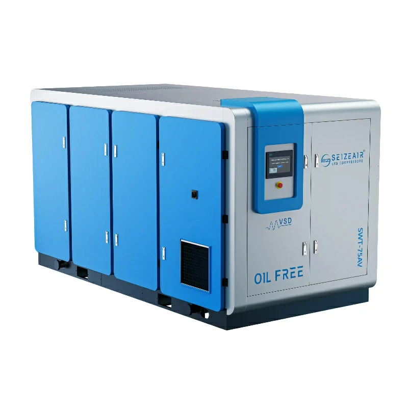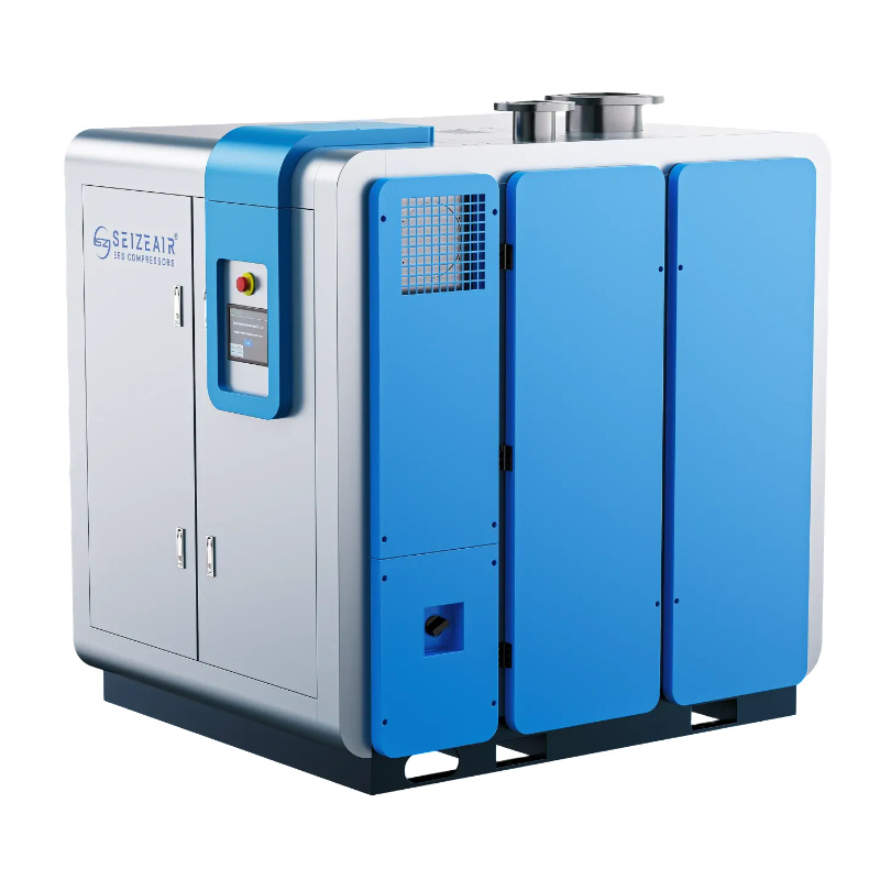


Industrial air compressor units drive modern manufacturing automation, yet selecting the optimal system requires balancing real-time volume demands against long-term operational expenses. Because electricity consumption represents roughly 80% of a compressor’s total lifecycle cost, choosing a poorly matched unit can cause excessive cycle times, rapid component wear, and thousands of dollars in annual energy waste. This guide breaks down high-efficiency system configurations, analyzes the essential engineering specifications your plant requires, and details how to optimize your compressed air infrastructure for peak efficiency and long-term reliability.
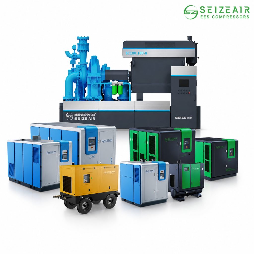
1. Why Choosing the Right Air Compressor Units for Manufacturing Matters
Every modern production floor relies on a steady, uninterrupted supply of pneumatic power to keep assembly lines running smoothly. When choosing heavy-duty machinery, selecting premium air compressor units prevents frequent industrial line stoppages by maintaining stable pressure across your entire automation network.
Failing to properly size your system leads to short-cycling, where the motor constantly turns on and off. This behavior draws massive spikes in electrical current, overheats the motor windings, and causes moisture to pool inside the compression chamber. Investing in high-performance hardware, such as a Seize Air system, protects your downstream equipment from contamination while keeping your monthly power draw as low as possible.
2. Which Air Compressor Unit is Best for Heavy-Duty Industrial Manufacturing?
When setting up a large facility, you must choose between rotary screw and reciprocating piston designs. Each handles continuous mechanical workloads differently.
Rotary Screw Systems
These machines use two helical rotors that spin continuously to trap and compress air. They are engineered for high-volume, uninterrupted factory usage.
- Duty Cycle: 100% continuous duty, allowing them to run 24 hours a day without needing rest periods to cool down.
- Performance: They deliver a steady, pulse-free stream of air, which prevents sudden pressure variations that can disrupt precise automated tooling.
- Maintenance Profile: Because the rotors never physically touch each other, internal friction is minimal, translating to fewer mechanical overhauls over a 10-year period.
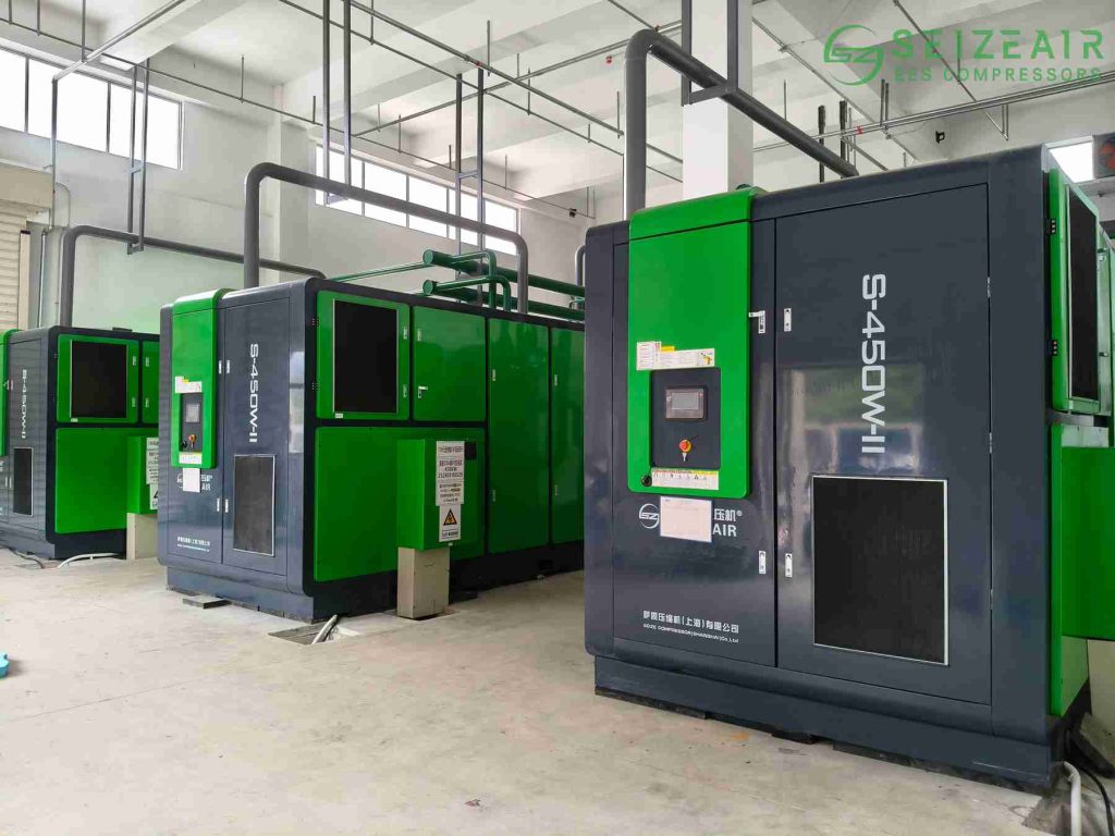
Reciprocating Piston Systems
These use a classic crankshaft and piston configuration to force air into a cylinder.
- Duty Cycle: Intermittent duty, usually capped at a 60% to 70% runtime profile to avoid thermal stress on the valves.
- Performance: They excel at generating very high pressures in short, intense bursts rather than continuous high-volume flows.
- Maintenance Profile: They contain more high-friction, wearing components like piston rings and wrist pins, which requires a tighter schedule for physical maintenance overhauls.
| Feature / Specification | Rotary Screw Compressor | Reciprocating Piston Compressor |
| Ideal Operational Load | Continuous, 24/7 operation | Intermittent, start-stop cycles |
| Energy Efficiency | High (especially with VSD models) | Moderate (efficient only for low-duty cycles) |
| Noise Level | Quiet (60 to 75 dB) | Loud (80 to 95+ dB) |
| Oil Carryover | Low (minimal oil mist in air) | Higher (requires robust filtration) |
| Lifespan | Very long (tens of thousands of hours) | Moderate (requires faster rebuilds) |
3. What is the Difference Between Fixed Speed and Variable Speed Drive (VSD) Compressors?
The electrical efficiency of your utility room hinges directly on how the drive motor reacts to changing production demands on the factory floor.
Fixed Speed Configurations
A fixed speed machine operates at one constant RPM whenever the motor is active. When your pneumatic tools stop drawing air, the machine shifts into an “unloaded” state. In this state, the inlet valve closes, preventing new air from entering, but the massive electric motor keeps spinning at full speed. During unloading, the unit still draws roughly 30% of its full-load power while producing absolutely zero usable compressed air. This wasted energy is called “idle load loss,” and it can silently add thousands of dollars to your monthly utility bills if your plant has fluctuating production schedules.
Variable Speed Drive (VSD) Systems
A VSD system utilizes a smart frequency inverter to continuously adjust the motor’s rotational speed, precisely matching your plant’s real-time air consumption. If only a single workstation is active, the motor runs at a slow crawl. If the entire second shift powers up, the motor scales up instantly.
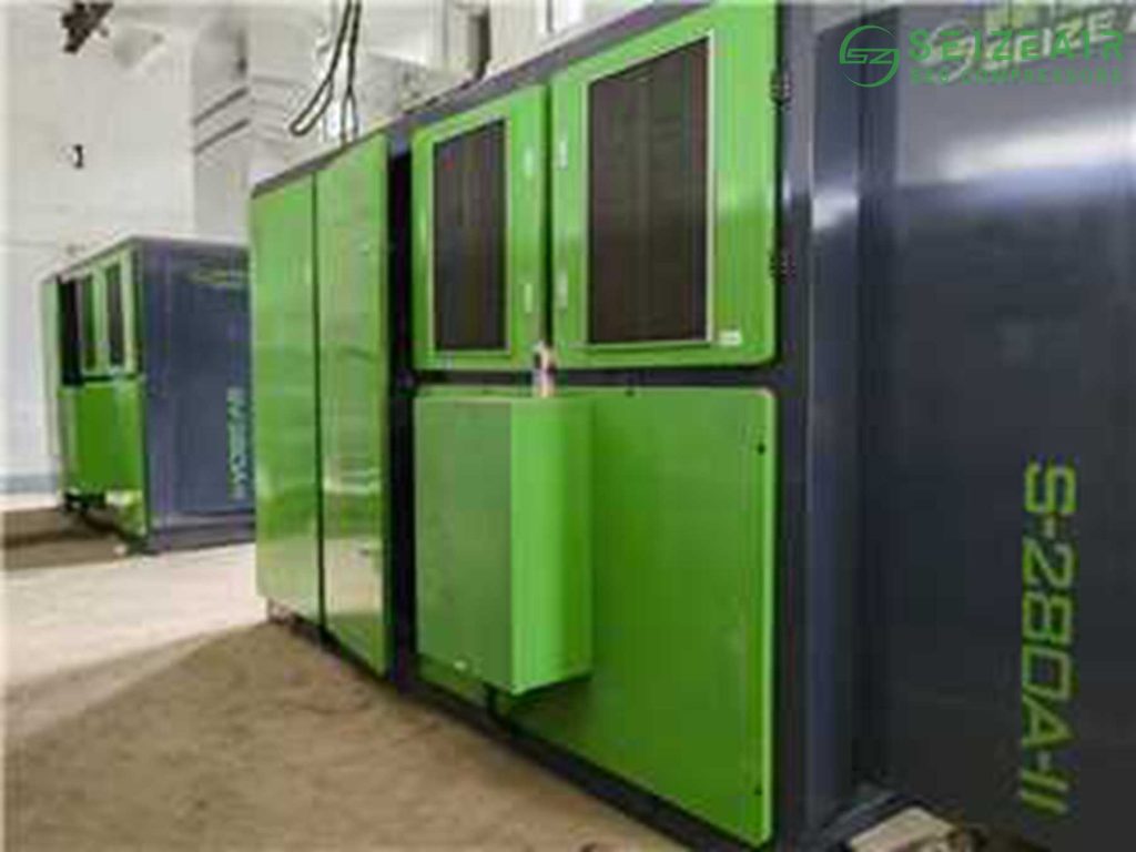
By eliminating the constant unloading cycles and heavy electrical current spikes during startup, a Seize Air VSD compressor can reduce energy consumption by up to 35% to 50% compared to a traditional fixed-speed unit. This makes it an incredibly effective tool for lowering a facility’s total operational overhead.
4. How Do I Choose the Right CFM and PSI for Industrial Air Compressor Units?
Sizing a compressor requires analyzing both volumetric flow and operational pressure. Confusing these two metrics can leave your plant underpowered or lead to excessive energy waste.
CFM (Cubic Feet per Minute) vs. PSI (Pounds per Square Inch)
- PSI (Pressure): This measures the mechanical force required to operate your tools. If an automated assembly arm requires 90 PSI to trip its internal actuators, your system must maintain at least 90 PSI at the tool inlet. Lower pressure will cause the tool to stall, while excessive pressure causes premature seal failures.
- CFM (Flow): This measures the volume of air delivered over time. CFM dictates how many tools you can run simultaneously. If your compressor cannot produce enough CFM, the overall system pressure will drop, starving downstream equipment.
Calculating Your Plant’s Real Air Requirements
To accurately size your system, do not rely on rough estimates. Create a detailed spreadsheet listing every piece of pneumatic equipment, its rated CFM consumption, and its precise duty cycle.
For example, if a sandblasting cabinet requires 40 CFM but only runs for 15 minutes out of every hour, its real-world duty cycle is 25%:
40 CFM * 0.25 = 10 CFM effective load
Sum the effective loads of all devices across the floor, then add a 20% safety margin. This margin accounts for inevitable network pipe leaks and allows you to install new production machinery in the future without needing to buy a completely new compressor.
5. Do I Need an Oil-Free or Oil-Lubricated Air Compressor for Manufacturing?
The internal design of the compression chamber dictates the purity of your air supply, splitting industrial systems into two distinct categories.
Oil-Lubricated Air Compressor
In these configurations, a fine mist of oil is injected directly into the compression chamber. This fluid seals the tiny clearances between the moving rotors, absorbs thermal energy generated by compression, and lubricates the bearings. While highly reliable and durable, these systems naturally carry a small amount of oil vapor into the air lines. This requires high-efficiency downstream filtration, making them the standard choice for heavy manufacturing, metal fabrication, CNC machine shops, and structural welding bays.
Oil-Free Air Compressor
These systems feature compression chambers that are completely dry. The moving parts rely on advanced low-friction coatings, like Teflon or specialized ceramics, rather than fluid lubrication. Because no oil ever enters the compression chamber, there is zero risk of oil mist slipping past downstream filters. This design is mandatory for strict manufacturing environments like pharmaceutical labs, electronics assembly, food and beverage packaging, and cleanroom semiconductor fabrication. In these industries, even a tiny speck of oil oil mist can contaminate an entire production batch, resulting in expensive product recalls.
| Application / Industry | Required Air Quality Class | Recommended Treatment Setup |
| Heavy Metal Fabrication | ISO Class 4 or 5 | Aftercooler + Coalescing Filter + Refrigerated Dryer |
| Automotive Robotic Painting | ISO Class 1 or 2 (Silicone Free) | High-Efficiency Filters + Desiccant Dryer |
| Electronics / Semiconductors | ISO Class 1 (Oil-Free/Ultra-Dry) | Oil-free Compressor + Multi-stage Filtration + Desiccant Dryer |
| Food & Beverage Packing | ISO Class 0 or 1 | Clean-Air Rated Compressor + Sterile Filters + Dryer |
6. What Air Treatment Accessories Do I Need for a Complete Manufacturing Setup?
Atmospheric air contains hidden water vapor, microscopic dust particles, and ambient chemical vapors. When a compressor pulls this air in and squeezes it, these pollutants become highly concentrated, creating an abrasive, corrosive sludge.
If this raw, untreated air travels down your lines, it will quickly rust out iron piping networks, degrade the delicate rubber seals inside automated cylinders, and ruin finished products by spraying water onto painted surfaces or clean components.
The Essential Air Clean-Up Components:
- Integrated Aftercoolers: These heat exchangers lower the temperature of the hot air leaving the compressor block. Dropping the temperature condenses up to 70% of the suspended water vapor into liquid water, which can then be safely ejected from the system through automatic mechanical drains.
- Coalescing Filtration Systems: These filters use a dense matrix of micro-glass fibers to capture tiny liquid droplets and solid dust particles, filtering out contaminants down to fractions of a micron.
- Refrigerated Air Dryers: These function like a heavy-duty refrigerator, chilling the compressed air down to roughly 35 to 38 degrees Fahrenheit. This drop in temperature forces the remaining moisture to condense out, achieving a stable pressure dew point suitable for general industrial applications.
- Desiccant Air Dryers: For specialized environments, these towers route the air stream through beds of moisture-absorbing chemical beads (such as activated alumina). They achieve ultra-low pressure dew points of -40 to -70 degrees Fahrenheit, ensuring the air is thoroughly dry for extreme cold-weather applications or sensitive electronic manufacturing.
7. How Does Smart IoT Integration Help Reduce Industrial Compressed Air Cost?
As manufacturing facilities shift toward smart factory automation, modern utility systems are replacing simple pressure switches with advanced microprocessors and Internet of Things (IoT) monitoring networks.
These onboard digital control modules continuously log critical performance data, including:
- Real-time air-end discharge temperatures
- Differential pressure across internal oil and air filters
- Running hours vs. actual loaded hours
- Multi-axis motor vibration profiles
By routing this data directly into your facility’s central SCADA management system or a secure remote mobile dashboard, maintenance teams can shift from reactive troubleshooting to highly accurate predictive servicing. Instead of waiting for a machine to overheat on a busy Tuesday afternoon, the smart controller can flag a rising temperature trend weeks in advance. This allows your team to schedule a quick 15-minute filter swap during a routine shift change, completely avoiding unplanned downtime.
8. What is the Best Piping Layout for an Industrial Air Compressor System?
Even a premium compressor will perform poorly if it is forced to push air through a bottlenecked, poorly engineered piping system.
Material Selection Matters
Avoid using standard black iron or galvanized steel pipes if possible. Over time, moisture in the line causes iron pipes to rust internally. This rust flakes off and travels down the line, clogging tool nozzles and damaging automated components. Galvanized coatings can also delaminate over time, sending sharp zinc scales straight into your pneumatic tools. Instead, choose smooth-bore, corrosion-resistant aluminum piping. Aluminum provides a lightweight installation, resists corrosion, and keeps friction low, ensuring optimal airflow throughout your facility.
The Benefits of a Closed Ring Main Layout
Never install your primary air lines in a long, single straight line that terminates at a dead end. Tools located at the far end of a straight line will suffer from severe pressure drops whenever tools closer to the compressor are running.
Instead, route your main air header in a continuous loop around the perimeter of the factory floor. This closed ring main design allows air to flow from two different directions to meet demand spikes. This balances air pressure across the entire facility and ensures that a machine at the far end of the plant receives consistent pressure, even during peak usage hours.
Proper Pitch and Moisture Management
Always slope your main overhead piping lines slightly downward (roughly 1 inch for every 10 feet of pipe run) away from the compressor room. Install vertical water-drop legs at the lowest points of the system, equipped with automatic electronic float drains. This setup forces remaining condensation to flow into the drop legs, keeping your primary overhead lines dry and free of standing water.
9. What is the Best Preventive Maintenance Schedule for Factory Air Compressors?
Protecting your investment requires a consistent, proactive maintenance plan. Catching minor wear early prevents it from snowballing into an expensive mechanical failure.
Daily Checks
- Check the physical oil level sight glass before starting the machine.
- Verify that automatic mechanical condensate drains are cycling properly and not stuck open or clogged.
- Check the digital control panel for active system warnings or maintenance alerts.
Weekly Upkeep
- Clean external air intake filters using low-pressure air to clear away ambient factory dust.
- Check manual moisture traps and drain legs across the plant floor.
Monthly Optimization
- Inspect the entire piping network for air leaks. Even a small 1/4-inch leak in a pressurized line can leak thousands of cubic feet of air, wasting significant electricity over a year.
Semi-Annual Deep Service
- Replace all inline filtration elements to prevent pressure drops.
- Send an oil sample to a lab for analysis. This helps detect early signs of internal bearing or rotor wear, allowing you to address issues before they cause a breakdown.
By partnering with a trusted manufacturer like Seize Air, you gain access to precision-engineered replacement parts and technical support networks. This support ensures your machinery operates at its original efficiency levels for decades to come.
Get Expert Guidance for Your Plant Setup
Finding the ideal balance between system performance, pressure stability, and long-term electrical savings requires specialized engineering insight. Our technical team at Seize Air is ready to review your manufacturing plant’s unique load profiles, run comprehensive system efficiency assessments, and configure a custom setup tailored exactly to your production demands.
[Contact our industrial air specialists today] to request an optimized equipment quote and start lowering your factory operating expenses.