
Stop chasing “cutting-edge” buzzwords. Let’s talk about torque, bearing loads, and air-end efficiency.
The industrial compressed air market is flooded with claims of “revolutionary” designs. But if you peel back the marketing, the core of any reliable, energy-efficient system is still the air end. For 80% of general industrial applications, from automotive assembly lines to food packaging plants, a single stage screw air compressor remains the most practical, cost-effective, and mechanically robust solution.
This article isn’t a general overview. It’s a deep dive into the mechanical logic, thermal dynamics, and engineering precision that separates a high-performance single stage unit from a mediocre one. We’ll examine specific parameters—pressure differentials, rotor tip speeds, and specific power (kW/m³/min) —and explain how these translate directly to your bottom line.
1. The Mechanical Reality: Why Single Stage Often Beats Multi-Stage
You might assume that adding compression stages automatically yields better efficiency. In large-scale, high-pressure applications (above 150 PSI or 10 bar), yes, multi-stage designs are necessary. But for the standard 7-8 bar (100-120 PSI) plant air network, a well-engineered single stage screw compressor offers several distinct advantages:
Fewer Moving Parts = Less Friction: A single stage air end has one compression chamber. This means one set of rotors, one set of bearings (often two on the drive side, one on the non-drive side), and a single gear set. Every additional stage introduces a gear box, an additional set of bearings, intercooler piping, and potential leak paths. Statistically, each moving interface is a failure point. Our in-house data at Seize Air shows that single stage units with optimized rotor profiles have a mean time between bearing failures exceeding 40,000 hours under continuous 24/7 operation—a figure we achieve through careful selection of SKF and NSK heavy-duty tapered roller bearings.
Lower Inlet Temperature = Higher Volumetric Efficiency: In a single stage, the incoming atmospheric air (typically 20-30°C) sees a single, direct compression event. There’s no intercooler to drop the temperature between stages. This sounds counterintuitive, but consider the P-V diagram of the compression cycle. A single stage screw compressor with a well-designed asymmetric rotor profile (like our “SEIZE” 5-6 lobe design) achieves volumetric efficiencies around 85-92% at 7 bar. The key is minimizing internal leakage (slip) between the rotors. This is a function of rotor clearance, which we hold to a tolerance of ±0.012 mm (12 microns) using 5-axis CNC grinding. That’s the precision engineering part.
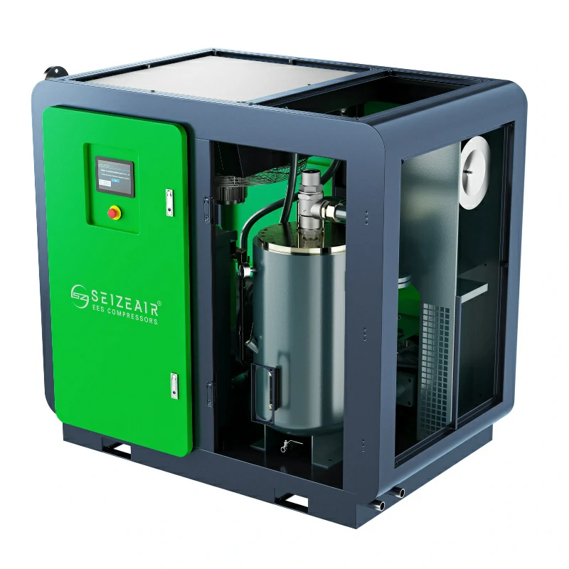
Compact Footprint & Simpler Piping: A single stage unit is physically smaller and lighter. The oil separator tank, cooler, and motor are all mounted on a single baseplate. This not only saves floor space (a valuable asset in any plant) but also reduces the length of interconnecting piping, which directly reduces pressure drop. Every 1 bar of pressure drop across a system wastes roughly 6-7% of the motor’s energy. A clean, direct pipe layout from air end to separator to cooler is a hallmark of good design.
2. The Energy Equation: Dissecting Specific Power (kW/m³/min)
This is the single most important metric for operating cost. It tells you how much electrical energy is consumed to produce one cubic meter of compressed air per minute. A typical, older screw compressor might run at 8.0-8.5 kW/m³/min. A modern, high-efficiency single stage unit should target 6.5-7.2 kW/m³/min under ISO 1217 conditions.
How does precision engineering achieve this?
Rotor Profile Optimization: The old “asymmetric” profiles (like SRM) were an improvement over symmetric, but they still had significant leakage paths. Modern profiles, like the one we developed at Seize Air, incorporate a “leading edge” sealing line design. This reduces the blowhole area—the primary source of internal leakage in a screw compressor. Our patented “Z-Type” rotor profile reduces blowhole area by about 18% compared to conventional SRM profiles, directly translating into lower specific power.
Oil Injection Strategy: The oil does more than lubricate. It seals the clearances, cools the air during compression (keeping discharge temperatures near 70-90°C, which is ideal for moisture removal), and absorbs heat. The injection pressure, quantity, and temperature are critical. We use a thermostatic bypass valve that maintains oil temperature at 45-50°C at the air end inlet. Too cold, and the oil becomes viscous, increasing drag and power consumption. Too hot, and the air’s moisture carrying capacity increases, leading to condensation in the separator. This single point (oil temp control) can account for a 2-3% difference in overall efficiency.
Motor and Drive Train: A direct-drive (flexible coupling) system, when properly aligned, has a mechanical efficiency of roughly 98-99%. However, a gear-driven unit offers more flexibility in rotor speed matching. We use helical gears made from 20CrMnTi case-hardened steel, with a AGMA Class Q10 accuracy rating. This ensures quiet operation (below 75 dB(A) at 1 meter for our 37 kW model) and minimal gear mesh losses. The motor itself should be a Premium Efficiency (IE4/IE5) design, as the motor usually accounts for 95% of the total compressor energy consumption.
3. Thermal Management: Why Your Compressor’s Heat is a Liability and an Asset
Heat is the enemy of reliability. Every 10°C rise in operating temperature halves the life of the lubricating oil and significantly increases the stress on the bearings and rotor surfaces.
The Role of the Oil Cooler: The oil cooler in a single stage unit must handle the full heat of compression (roughly 75% of the motor input power is rejected as heat). A poorly designed cooler, or one with fin spacing that’s too tight for a dusty environment, will cause the compressor to overheat, triggering a shutdown or forcing it to run at a lower efficiency. We employ a “low temperature differential” design with a 10°C approach (the oil leaving the cooler is only 10°C hotter than the ambient cooling air). This requires a larger cooler, but it ensures consistent performance even when ambient temperature hits 40°C.
Automatic Thermal Management: The bypass valve we mentioned earlier isn’t just about energy. It’s about dew point control. In a single stage unit, the compressed air leaving the separator is often at 75-85°C. As it passes through the aftercooler, its temperature drops to ambient + 10°C. If the ambient air is 25°C, the air leaving the aftercooler is 35°C. The pressure dew point of this air is roughly 38-42°C at 7 bar. If you don’t have a refrigeration dryer, this is the critical temperature above which condensation will form in your pipes. A well-designed system manages this thermal profile to minimize condensate formation in downstream piping, reducing corrosion and pressure drops.
4. System Integration: Beyond the Compressor Package
A single stage screw compressor, no matter how well-built, is only one part of a compressed air system. The real-world efficiency depends on how it integrates with the rest of the plant.
Variable Speed Drive (VSD) vs. Fixed Speed: A fixed-speed (on-line/off-line) compressor is fine for base loads, but if your demand fluctuates by more than 20%, a VSD is essential. However, the VSD itself introduces losses (typically 3-5% at full load, but increasing at lower speeds). The sweet spot for a VSD on a single stage screw is operating between 30% and 100% of its flow capacity. Below that, the magnetic losses in the motor and the drive’s switching losses become disproportionate.
The “Plumbing” is Part of the Engineering:
Piping Size: The rule is simple: keep the pressure drop below 0.1 bar across the main header. For a 100 m³/min system, that likely means a DN150 (6-inch) pipe.
Piping Material: Galvanized steel is common, but it can flake over time. Aluminum or copper is preferred for sensitive applications (food, electronics) where rust particles are unacceptable.
Receivers: A properly sized air receiver acts as a buffer. For a single stage unit, a receiver volume of roughly 0.5-1.0 gallon per CFM is a good starting point. This allows the compressor’s pressure control system to respond to demand swings without “short cycling” (starting/stopping too frequently), which wears out the motor contactor and the unloader valve.
5. The Human Factor: Why a 40,000-Hour Bearing Life Matters
Let’s move from theory to practice. Since 2009, Seize Air has designed and manufactured over 40,000 single stage screw compressors. We’ve learned that the number one cause of unplanned downtime isn’t the rotor, the bearings, or the motor. It’s the seals.
The Shaft Seal: The main shaft seal (often a lip seal or a mechanical seal) is the weakest point on the air end. It must withstand oil pressure, oil temperature, and shaft rotation at up to 3,000 RPM. A single failure here means an oil leak, which is messy, dangerous (slippery floors), and costly. That’s why we use a double-lip, silicon carbide mechanical seal with a built-in “sealing gas” port. This allows a slight positive pressure to be applied to the seal’s back side, preventing oil from ever reaching the atmosphere. It’s a small detail but adds thousands of hours of leak-free operation.
Bearing Selection and Preload: The drive-side bearing must handle the massive axial thrust load generated by the air pressure (roughly 7-8 bar of pressure pushing the male rotor axially). We use SKF 222 series spherical roller bearings with a C3 clearance. These are preloaded to a specific torque value (measured in Nm) during assembly using a precision torque wrench. Under-loading leads to vibration; overloading leads to overheating. This is a 20-minute process that many manufacturers skip. We don’t. The result is a vibration level of less than 2.5 mm/s RMS, far below the ISO 10816-3 limit of 4.5 mm/s for rigid machines.
6. Real-World Case: A Textile Mill’s Energy Savings
A practical example: A textile mill in Bangladesh was using a 20-year-old, 250 kW single stage screw compressor for their looms and dyeing process. Their specific power was a painful 8.8 kW/m³/min. They were paying roughly $120,000 per year in electricity for this one machine.
They contacted Seize Air. We performed a system audit (free of charge). The audit revealed:
A massive pressure differential (1.2 bar) across their aging piping.
An undersized receiver (5 months of production lost to short cycling).
The compressor’s air end was worn, with rotor clearances exceeding 0.15 mm (causing high internal leakage).
We recommended replacing it with a Seize Air SVC-250W single stage VSD unit (250 kW, 7 bar). Our unit, with its Z-Type rotor profile, IE5 motor, and optimized oil system, achieves a specific power of 6.9 kW/m³/min.
The result after 6 months of operation?
Energy Consumption: Dropped from 8.8 to 6.9 kW/m³/min. That’s a 22% reduction.
Annual Savings: Over $26,000 per year in electricity.
Maintenance Costs: Our unit requires an oil change every 8,000 hours (vs. 4,000 for the old unit) and the bearing set is rated for 40,000 hours.
This wasn’t a “cutting-edge” magic solution. It was simply engineered precision applied to a well-understood mechanical principle—the single stage screw. That’s the payoff of good engineering.
Conclusion: The Bottom Line on Single Stage Precision
For the vast majority of industrial applications, a professional single stage screw air compressor isn’t a compromise. It is the optimal engineering solution. It offers the best balance of energy efficiency, reliability, purchase cost, and serviceability when compared to multi-stage or centrifugal alternatives.
The difference between a good unit and a great one lies in the details: the rotor profile’s blowhole area, the bearing preload torque, the oil temperature control, and the seal design.
At Seize Air, we don’t sell “magic.” We sell measurable performance backed by 15+ years of precision manufacturing in Shanghai. Our 40,000+ units operating globally are a testament to this philosophy. If you need a single stage screw compressor that delivers consistent, low-cost compressed air for the next 15+ years, look beyond the brochure. Look at the bearing specifications, the rotor profile, and the specific power. That’s where the real engineering lives.
Ready to stop your energy waste? Contact us for a free system audit. We’ll measure your current specific power and show you the math. No fluff. Just engineering.