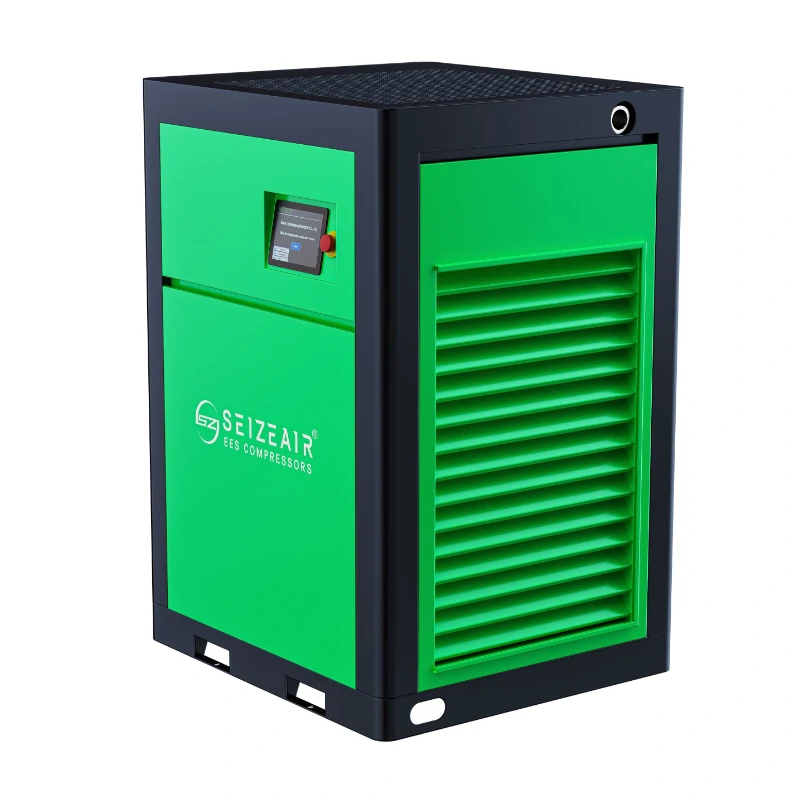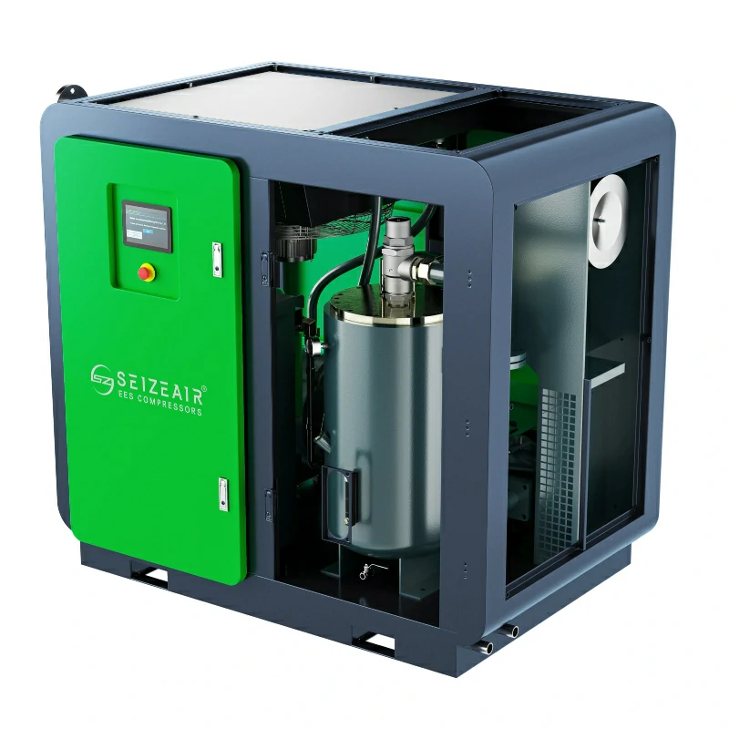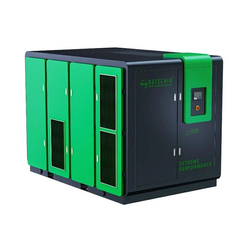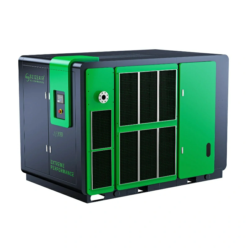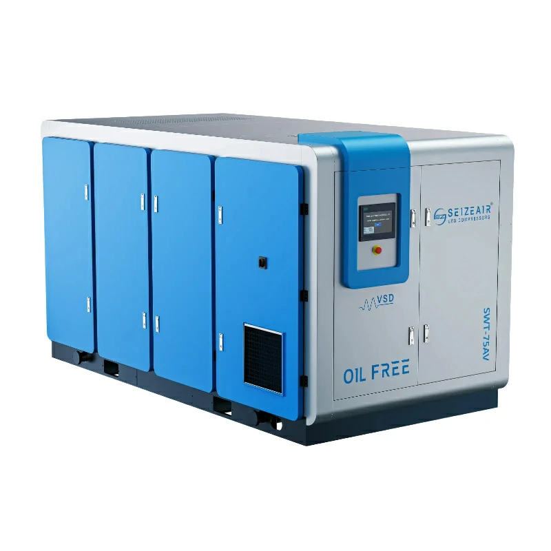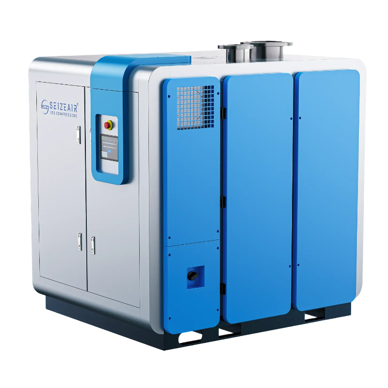


Air compressor for glass manufacturing is a system decision rather than a single machine order: forming, mould cooling, conveying and inspection each demand a different pressure, flow and cleanliness, while the furnace keeps running whether the compressor room is ready or not. This guide shows plant engineers and buyers how to map those users, assign an air-quality class at every point of use, build a defensible demand profile, choose a compression technology for each pressure band, and write an acceptance test that protects production before the first bottle or sheet leaves the line.
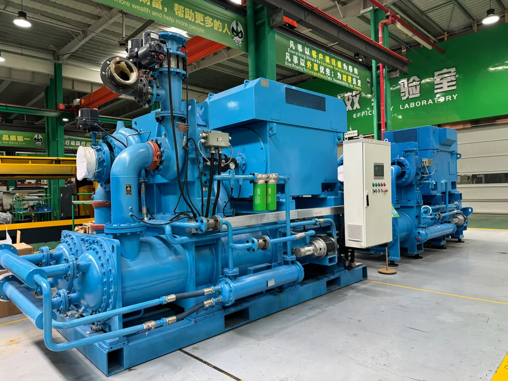
Why Does Glass Manufacturing Need a Dedicated Compressed Air Plan?
What Makes a Glass Line Different From a General Factory?
Compressed air touches almost every stage of a glass works. Raw material handling moves sand, soda ash, limestone and cullet; combustion and burner systems need a controlled air supply; forming uses air to settle the gob, shape the parison and finish the container; mould cooling, annealing lehr control, cutting, grinding, inspection, leak testing, coating, cold-end handling and palletising all draw on the same station. A general engineering workshop may treat compressed air as a convenience. A glass plant has to treat it as a process utility with a quality specification.
The distinction matters because a failure rarely stays local. A short pressure dip during a forming cycle does not just slow one machine; it can affect an entire production section, and the hot end cannot be paused while the compressor room is reset. Industry discussion of the sector’s energy pressures in glass manufacturing usually concentrates on the furnace, but the same continuity requirement reaches every utility that feeds it.
Start the project by writing down what compressed air actually does on your site. Plant drawings are often out of date, and a line added during an expansion may share a header that was sized for a different duty. Walk the line with operations staff, note every point where air is consumed, and mark which points are shared between production areas. That list, not a catalogue, is the starting point for everything that follows.
Which Air Users Belong in the Same Supply Group?
Divide the list into three groups. Process-contact air touches the glass surface, a mould, a coating head or a test circuit, so product engineering owns its quality requirement. Instrument and automation air feeds valves, cylinders, plungers and positioners, which need clean, dry air at a stable pressure. General utility air covers dust collector pulse jets, pneumatic tools, cleaning and packing equipment, which are usually more tolerant of both moisture and pressure variation.
Grouping is not an academic exercise. Treating all three as one header forces you to buy the highest grade of air for the least demanding user, or to accept a grade that damages the most demanding one. A split header with a common, well-treated station and local polishing at critical points is often easier to justify to a quality team than a single blanket specification applied across the whole factory.
Record each group as a short table before any supplier discussion: point of use, required pressure at that point, applicable cleanliness class, and the department that owns the requirement. Ownership matters more than it appears. A coating adhesion defect is investigated by quality engineers, while a sticking plunger is investigated by maintenance, yet both trails lead back to the same compressor room and the same treatment train.
Why Does Uptime Outrank Nameplate Efficiency?
A glass furnace runs continuously once lit, and forming machines are paced to that furnace. Published industry descriptions of glass plants repeatedly stress that unplanned compressor downtime is unusually expensive, because the hot end cannot simply stop and restart around a utility fault. That single fact should shape the specification more than any full-load efficiency figure on a datasheet.
Ask the awkward question early: what happens when one package trips at three in the morning? The answer needs an automatically starting standby machine, a visible readiness signal, isolation valves that let one unit be worked on, and a control sequence that survives the loss of any single unit. Our guide to choosing a heavy-duty compressor for continuous operation covers the same reasoning for other non-stop processes.
Efficiency still matters, but it has to be evaluated across a defined running year with a measured load profile. A very efficient machine with no credible standby arrangement is a poor purchase for a glass works. Conversely, redundancy that is specified without understanding demand can leave an idle asset that nobody rotates, tests or maintains. Both decisions belong in the same document.
What Air Quality Does a Glass Plant Need?
How Should You Read ISO 8573-1?
ISO 8573-1 expresses compressed air purity as three classes, in the order particles, water and oil. It is a specification language, not a certificate that a buyer accepts once and then forgets. A class applies at a defined point of use under defined conditions, so the first question is always where that class has to be met. A figure measured at the dryer outlet says nothing about what arrives at a forming tool after fifty metres of uninsulated pipe.
Industry references on hollow glass commonly describe the lower-pressure forming circuit around Class 1:4:1 and the higher-pressure circuit around Class 1:2:1, with drying to roughly minus 40 C and lower still for critical duties. Treat those as published examples of how other plants write a specification, not as a universal requirement for your line. Your forming machine manual, coating supplier and quality department define the numbers that actually bind you.
The Compressed Air and Gas Institute publishes guidance on air-quality classification and testing language that helps buyers ask comparable questions of every supplier. Require each bidder to state the class, the measurement method and the measurement point in writing. A class quoted without a location, a test method and a load condition is a marketing phrase rather than a specification.
Where Do Oil, Water and Particles Show Up as Defects?
Oil aerosol and vapour are the classic enemies of hot glass. Trace oil can make a gob stick in the mould, leave a visible surface blemish, weaken the adhesion of a coating, or contaminate an inspection circuit. Water arrives as condensate: it corrodes pipework, makes precision valves stick, disturbs a counter-blow sequence and can affect flame stability where air supports combustion. Particles scratch soft surfaces, block small nozzles and plug the orifices that control a forming cycle.
None of these failure modes is dramatic at first. A small increase in rejected ware, a slightly longer cycle, a valve that needs cleaning more often: the cost accumulates quietly until someone correlates it with a dryer that has been saturated for weeks. That is why the quality requirement and the maintenance plan have to be written together, and why differential-pressure and dew-point indication belong in the design rather than being added later.
| Contaminant | Where the damage appears | Control to specify |
|---|---|---|
| Oil aerosol and vapour | Mould sticking, surface blemishes, poor coating adhesion, contaminated condensate | Oil-free generation at contact-critical points, or a validated coalescing and activated-carbon train with a stated class |
| Water and condensate | Corrosion, sticking valves, inconsistent blow and counter-blow, fluctuating combustion air | Drying to an agreed pressure dew point at the point of use, working drains, monitored dew point |
| Solid particles | Scratched surfaces, blocked nozzles, plugged control orifices | Intake filtration plus point-of-use particulate filtration, with differential-pressure monitoring |
| Microbiological or ambient dust | Contamination of inspection and test circuits, filter loading near the batch house | Intake placement away from dust sources, sealed pipework, documented filter replacement triggers |
Should the Whole Plant Be Oil-Free?
Not necessarily, and the answer depends on where the air goes. Air that touches hot glass, a mould surface, a coating head or a leak-test circuit is a candidate for oil-free generation, or for a treatment train that has been validated against the required class. General pneumatic power, pulse-jet cleaning and cold-end packing are often served more economically by oil-injected machines with properly selected downstream drying and filtration.
Where oil-free generation is chosen, both dry screw and water-lubricated designs are available, and the differences between Class 0 water-injected and dry machines are worth reading before the enquiry. Certificates for the dry oil-free screw and water-lubricated ranges are issued against ISO 8573-1:2010 with ISO 8573-2:2018 and ISO 8573-5:2001; each one lists the models it covers and a validity date. Check that list against the exact model offered. A series-level claim is not a model-level claim.
A dedicated dry oil-free screw compressor range can also serve one sensitive cell, so the rest of the plant does not pay for a grade it never uses. That split is usually more practical than converting an entire station, provided the two networks are clearly labelled and protected against a cross-connection that would bypass the treatment.
How Do You Place the Treatment Train?
Decide where drying, filtration and storage sit relative to the split headers. A common arrangement treats all air centrally to a defined baseline, then adds local polishing immediately before the most sensitive users. This keeps the capital cost of high-grade filtration proportionate while still protecting the points that actually need it. Put the receiver after the dryer where the design intends dry storage, and provide test points on both sides of every major component.
A compressed air dryer selection guide helps frame the choice between refrigerated and adsorption drying, but the deciding inputs are your required pressure dew point, inlet temperature, real demand pattern and allowable pressure loss. Ask for dew-point indication and differential-pressure indication so a saturated bed or a loaded element becomes a maintenance signal, not a product defect discovered by the quality lab.
Never install a permanent bypass around a dryer or filter for start-up convenience. A bypass left open is the fastest route to a quality incident, and it also invalidates the acceptance records you will rely on when something goes wrong. If a temporary bypass is genuinely needed during commissioning, make its removal a signed line item in the handover checklist.

What Pressure and Flow Should You Specify?
Why Do Container-Glass Plants Use Two Pressure Bands?
Published descriptions of hollow-glass production describe a two-pressure arrangement. A lower band, commonly cited around 3 bar, handles gob settling, pre-blow, parison forming and the large air volumes needed for mould cooling and cleaning. A higher band, commonly cited around 7 bar, delivers the final blow and powers counter-blow, plunger mechanisms, automation and instrumentation. Producing the lower band directly avoids spending compression work on air that never needs to reach the higher pressure.
Two cautions apply. Those figures come from published industry descriptions, not from your machine nameplates, and float glass, fibreglass, tableware and speciality glass lines do not necessarily share the same arrangement. Confirm the actual values in the forming machine manual, then verify them at the machine inlet under production conditions before they enter an enquiry. A number copied from a general article is not a design input.
The layout below is deliberately simple. Its purpose is to make the split visible to everyone involved in the purchase, from the process engineer to the contractor installing the headers. Measurement points belong at each branch, because the pressure that matters is the one at the machine, not the one displayed on the compressor controller.
[compressor station] -- [receiver + dryer + filtration]
        |
        +-------------------+--------------------+
        |                                        |
 [low-pressure header]              [high-pressure header]
 (pre-blow, parison,                 (final blow, counter-blow,
  mould cooling, cleaning)           automation, instruments)
        |                                        |
 [local filter + test point]        [regulator + filter + test point]
        |                                        |
  forming tools                      IS machine / cold end
How Do You Build a Demand Profile Without Inventing Numbers?
Start with documents, not estimates. For every user, collect the required inlet pressure, the flow at that pressure, the duty cycle within a forming cycle, and the allowed pressure fluctuation. Nameplate data from the machine supplier is the starting point; a recording flow meter and pressure logger at the station outlet show what the plant really draws when several lines run together.
A short measurement campaign during representative production is more useful than a theoretical sum, because it captures overlap. Record compressor loading states, dryer purge events and unusual demand such as a line change, a mould swap or a cleaning cycle. Label every reading with location, units and whether pressure is gauge or absolute. Synchronised readings on the same operating event are the only ones that can be compared honestly.
A screw compressor sizing guide covers the conversion from measured demand to machine selection. Keep the arithmetic in plain text and keep the assumptions visible: Total design flow = sum of continuous users + coincident peak demand - documented diversity + reserve margin. Reserve margin is an engineering decision based on measurement uncertainty and future approved expansion, not a fixed percentage copied from a brochure.
Do not let a supplier fill in your operating hours, electricity tariff or ambient temperature on your behalf. Those inputs belong to your plant. If they are not yet available, say so and ask for a model that accepts your numbers later. An impressive-looking calculation built on invented inputs is worse than no calculation at all, because it gives the project team false confidence.
Which Supply Bands Should the Enquiry Separate?
The grid below is a working template rather than a set of values to copy. Replace every example with the figure measured or specified at your own plant before it goes to a supplier.
| Supply band | Typical users described in glass literature | What you must verify locally |
|---|---|---|
| Lower band, around 3 bar in published container-glass descriptions | Gob settling, pre-blow, parison forming, mould cooling, cleaning volumes | Machine manual pressure at inlet, peak volume during the forming cycle, allowed fluctuation |
| Higher band, around 7 bar in published descriptions | Final blow, counter-blow, plunger mechanisms, automation, instrument air | Simultaneous demand of several sections, regulator and valve losses, quality class at the tool |
| Very low pressure, at or below 2.0 bar | Combustion support, cooling air, batch material conveying | Actual discharge pressure and inlet conditions; keep on a separate, labelled header |
| Station outlet to machine inlet | Not a user, but the most commonly ignored pressure loss | Measured differential across headers, branches, filters, hoses and couplings |
What Does Storage Actually Fix?
A receiver buffers short, sharp demand events and gives the controls time to respond. It does not repair a chronic capacity shortfall, an undersized main, a saturated dryer or a restriction in a branch line. Treat storage as part of the control response rather than as extra compressor capacity; adding a tank to a station that cannot meet its base load simply delays the pressure decay.
Sizing depends on the event duration, the allowable pressure drop at the machine and the recharge behaviour of the station, all of which can be measured or specified. Pressure-vessel registration, relief devices, automatic drainage and the physical location of the receiver belong in the same discussion, with the responsible engineer signing off the arrangement before it is ordered.
Where Is the Blower and Compressor Boundary?
Confusion here causes expensive mistakes, because a blower and a centrifugal compressor are not interchangeable pressure sources. Verified catalogue ranges for the relevant series are: magnetic-levitation centrifugal blowers at 0.3 to 1.2 bar and 22 to 400 kW; oil-free screw blowers at 0.4 to 2.0 bar and 22 to 250 kW with 60 to 100 percent speed regulation; gear centrifugal compressors at 1.5 to 16 barG, 40 to 380 m3/min and 100 to 2200 kW, built to API 672 with AGMA Q4 balancing.
A forming circuit described at around 3 bar therefore cannot be fed by a 1.2 bar blower, and feeding a 0.8 bar combustion-air duty from a 7 bar header through a reducing valve wastes the work already spent compressing it. Match the machine to the band, then check the model-specific table for the flow available at your actual discharge pressure. Series cover ranges describe a product family, not every possible combination of pressure and flow.
Reference conditions matter as well. Capacities in these ranges are stated to ISO 1217 Annex C at 1 bar and 20 C, with altitude and ambient limits specified in the manuals. A flow quoted at a different inlet condition is not comparable. Ask each bidder to restate capacity at your site conditions, including altitude, before any comparison is made.
Which Pressure Should the Enquiry State?
State the required pressure at the point of use, the allowable loss from the station outlet to that point, and the location where compliance will be measured. Add the minimum and maximum simultaneous demand, site ambient and intake conditions, altitude, available electrical supply, the quality class for each group, and the redundancy requirement. Include the treatment scope and the documentation you expect at handover.
A line that says “7 bar air compressor” is not a specification. It hides the difference between discharge pressure at the package and pressure at the machine inlet, which is where the forming process actually lives. Vendors can only be compared fairly when every bid is priced against the same duty, the same reference conditions and the same scope of supply.
Which Compressor Type Fits Each Glass Plant Duty?
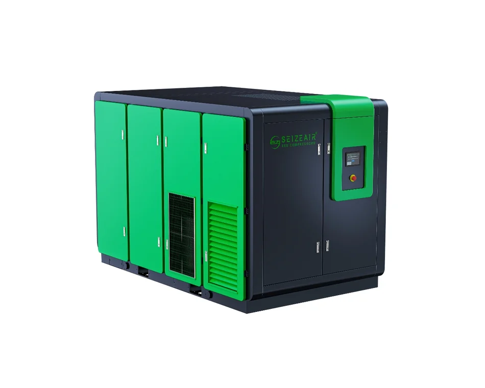
When Is an Oil-Injected Screw the Right Base Machine?
For utility air and general pneumatic power, an oil-injected screw with correctly selected drying and filtration remains the workhorse. It is compact, tolerant of changing demand and straightforward to maintain, which suits the mixed loads of a cold end where conveyors, handlers and packing machines come and go. Treatment quality, not the compressor alone, determines whether that air is acceptable at the point of use.
Where the base load is steady and high, a two-stage oil-injected screw compressor splits the pressure ratio across two compression steps. The benefit is not a universal saving percentage; it is a different efficiency shape at a defined pressure ratio and load. Ask for specific power at your actual discharge pressure and compare like with like, including the input power definition.
If the measured profile has a pronounced variable component, a VSD screw compressor can trim output without repeated loading and unloading. Whether that is worthwhile depends on how many hours the plant actually spends at part load, a number that must come from your own logging rather than from an assumed curve. A VSD unit on a genuinely constant load has little to modulate.
When Does Oil-Free Generation Make Sense?
Use oil-free generation where air may contact the product, a mould surface, a coating head or a test circuit, and where a validated filtration train is not acceptable to the quality team. Verified catalogue scope for the dry oil-free screw range is 37 to 450 kW and 4.5 to 10.5 bar, with two-stage and three-stage arrangements and testing to ISO 1217 Annex C at 1 bar and 20 C. Oil-free scroll units cover smaller point-of-use duties at 7.5 to 37 kW, 0.8 to 4.0 m3/min and 8 bar.
Those are series ranges, not a promise that every flow and pressure combination exists. Request the exact model row, including capacity at your working pressure, and confirm that the offered model appears on any Class 0 certificate you intend to rely on. Certificate scope and validity dates are model-specific, and a certificate for one variant does not automatically extend to a larger frame in the same family.
A point-of-use oil-free unit sometimes costs less than upgrading an entire station. Compare the two arrangements on installed cost, service access and the consequence of a treatment failure, rather than on a single purchase price. Where a quality incident would scrap a full batch, the extra cost of generation-side cleanliness is often easier to defend.
When Does a Centrifugal Machine Earn Its Place?
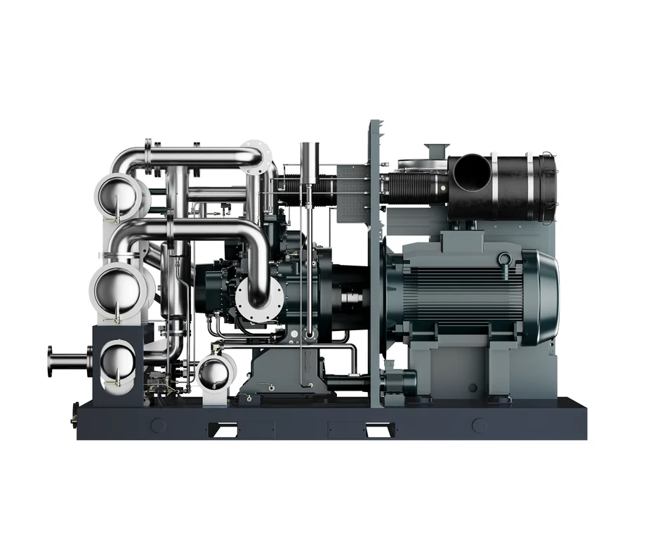
Large, steady base loads are the natural territory of a gear centrifugal air compressor. The verified series range of 40 to 380 m3/min at 1.5 to 16 barG and 100 to 2200 kW suits a hot end that draws a broadly constant volume hour after hour, and the package is oil-free by construction rather than by downstream clean-up.
Centrifugal machines have a turndown envelope and a surge line. If your measured profile swings sharply between shifts, during line changes or at start-up, the control strategy and the number of machines have to be designed around that behaviour. Do not assume that a full-load efficiency figure describes the whole operating year, and ask the supplier to show the acceptable operating envelope in writing.
API 672 and AGMA Q4 balancing are useful procurement checkpoints for the machine itself, but they say nothing about the dryer, receiver, header or standby arrangement. Specify the whole station. A well-built centrifugal package feeding an undersized or wet distribution system will still deliver poor air at the tool.
What About Low-Pressure Blowers in a Glass Works?
Combustion support, process cooling, pneumatic conveying of batch materials and certain cleaning duties sit at much lower pressure than forming air. A blower in the 0.3 to 1.2 bar or 0.4 to 2.0 bar band supplies that volume without first compressing it to 7 bar. Keep such a machine on a separate header and label both systems clearly, because an accidental cross-connection can damage low-pressure equipment and confuse operators.
State the required flow at the actual discharge pressure and inlet condition. Blower capacity changes considerably with pressure, so a single “maximum flow” figure from a brochure cannot size the duty. Ask for the performance curve and the motor rating at your operating point, then check the part-load behaviour if the conveying or cooling demand varies through the shift.
How Do You Compare the Options Fairly?
A comparison is only fair when the duty, the reference conditions and the scope of supply are identical for every bid. The grid below sets out the machine families alongside the ranges that could be verified against dated catalogues.
| Machine family | Verified series range | Where it fits in a glass plant | What to check before ordering |
|---|---|---|---|
| Oil-injected screw, single or two stage | Series tables vary by model; two-stage ranges split the pressure ratio | Utility air, cold-end pneumatics, steady base load | Capacity and input power at your working pressure; treatment scope; standby arrangement |
| Dry oil-free screw | 37 to 450 kW, 4.5 to 10.5 bar, ISO 1217 Annex C | Contact-critical process air, coating and test circuits | Exact model row; Class 0 certificate scope and validity; cooling water or air requirement |
| Oil-free scroll | 7.5 to 37 kW, 0.8 to 4.0 m3/min, 8 bar | Small local point-of-use duties, laboratories, isolated cells | Whether one central treatment train or several local units is more economical |
| Oil-free screw blower / magnetic-levitation blower | 0.4 to 2.0 bar, 22 to 250 kW / 0.3 to 1.2 bar, 22 to 400 kW | Combustion support, cooling, batch conveying | Flow at actual discharge pressure; inlet conditions; separate labelled header |
| Gear centrifugal compressor | 1.5 to 16 barG, 40 to 380 m3/min, 100 to 2200 kW | Large steady hot-end base load | Turndown envelope, surge protection, sequencing with trim machines, station scope |
What Should the Comparison Grid Include?
Put every option into the same table with the same reference conditions, then add the columns that usually decide the purchase: standby arrangement, service access, treatment scope, and exactly what is included in the quoted specific power. Numbers from different catalogues are not comparable until their inlet conditions, pressure and power definitions have been aligned.
SEIZE AIR publishes model-level tables for each series; ask for the relevant dated page rather than a summary slide. Any figure that cannot be traced to a dated catalogue and a named model should be marked as unconfirmed until the supplier provides it. That habit protects both the buyer and the engineer who has to defend the selection a year later.
How Do You Keep the Air Supply Running When the Furnace Never Stops?
What Does N+1 Mean in a Compressor Room?
N is the number of packages needed to meet the design flow; the extra one is a machine that can carry the load when any single unit is stopped. In a continuously operating glass works, that standby unit should be able to start automatically on a pressure or status signal, and its readiness should be visible in the control room rather than discovered during a fault.
Rotation matters as much as redundancy. A standby machine that never runs develops its own faults, so the sequencer should rotate duty and log running hours. Isolation valves, non-return valves and where practical a split electrical feed let maintenance work on one package without dropping the header. Draw the maintenance state as well as the normal state; a station that can only run one way is fragile.
        +-----------+   +-----------+   +-----------+
        | Unit 1    |   | Unit 2    |   | Unit N+1  |
        | base load |   | base load |   | standby   |
        +-----+-----+   +-----+-----+   +-----+-----+
              |               |               |
        ======+===============+===============+======  common header
                              |
                    [receiver + treatment]
                              |
              +---------------+----------------+
              |                                |
     low-pressure branch             high-pressure branch
     (auto-start on pressure)        (auto-start on pressure)
How Should Sequencing and VSD Interact?
A common arrangement lets one variable-speed unit absorb the fluctuating portion of demand while fixed-speed machines carry the steady base. The sequencer decides which unit loads, unloads or stops, and it should prevent several machines unloading at the same time. That sounds simple, but the logic has to reflect the real demand pattern, including short forming peaks and dryer purge cycles.
Setpoints deserve the same discipline as the rest of the specification. Record the target pressure band, the timer values, the sensor locations and the changeover logic, then test them deliberately during commissioning. A sequence that looks correct on a drawing can still hunt during a brief peak if the timers were chosen by guesswork or the pressure sensor sits too far from the header.
What Alarms and Records Matter?
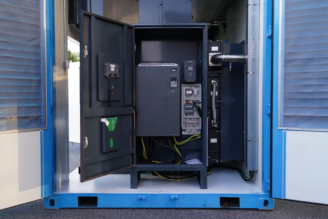
At minimum, trend header pressure at the station and at a representative machine inlet, pressure dew point after drying, differential pressure across filter elements, package discharge temperature, and the running status of every unit. Alarms should reach someone who can act, with a recorded response and a clear escalation path when the standby machine is already running.
Keep a short event log: what tripped, when, what the production state was, and what changed afterwards. That record turns a one-off incident into a defensible design input for the next expansion. It is far more useful than a service report that only says the unit was reset, and it also shows whether an alarm is genuinely actionable or merely noise that operators have learned to ignore.
How Do You Plan Condensate and Drain Reliability?
Condensate is produced whenever air is compressed and cooled. Failed automatic drains are a common cause of water carry-over, so specify accessible, monitored drains and include a manual check in the maintenance round. Oil-contaminated condensate from an oil-injected station is a different waste stream from the condensate of an oil-free machine, and the two should not be piped into the same untreated drain.
Disposal rules are local. Consult your site environmental permit and the authority that issued it; general guidance on industrial discharges is available from organisations such as the US Environmental Protection Agency. Do not assume that a treatment arrangement accepted in one country is automatically acceptable in another, or that a separator sized for one station covers a later expansion.
What Does a Glass Plant Compressor Room Have to Handle?
Where Should the Intake Air Come From?
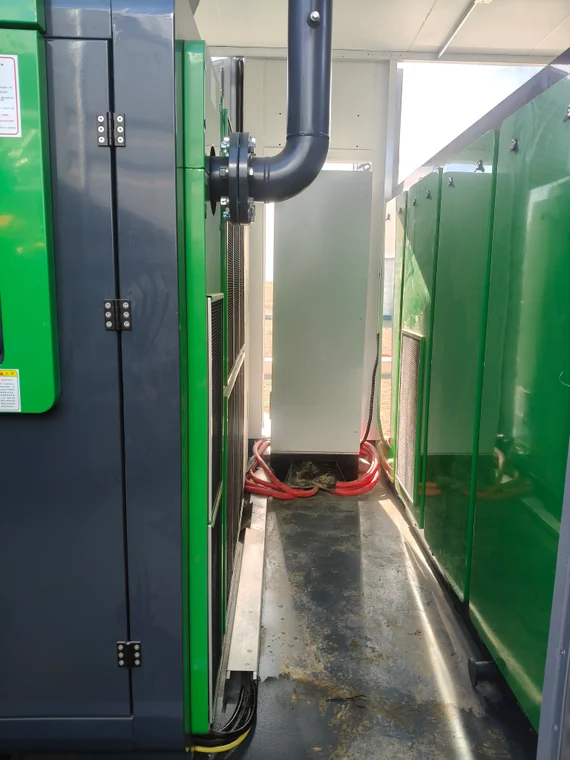
Batch plants generate fine mineral dust from sand, soda ash, limestone and cullet. Intake filtration and intake placement are therefore design decisions, not afterthoughts. Locate the inlet away from dust sources, vehicle routes and furnace exhaust, and make the filter elements easy to inspect without dismantling the package. A remote intake with a clean, cool air supply often pays for itself in element life and stable performance.
Dust loading changes the maintenance interval. Agree a differential-pressure indication and a cleaning or replacement trigger with the supplier, then check it against actual conditions during the first months of operation rather than adopting a generic schedule. Where the batch house and the compressor room share a wall, expect the intake filters to tell you something useful about the building layout.
How Much Heat and Ventilation Does the Room Need?
A 2021 English oil-injected operating manual lists an installation range of minus 5 to plus 40 C, relative humidity below 85 percent, altitude below 1000 m and duct air velocity not exceeding 4 m/s. That is a version-specific manual range, not a current universal rating. Obtain the latest installation instructions for the offered model before the room is designed, and record which version you used.
Ventilation design follows the heat rejected by the installed machines. Bring cool air in low, take hot air out high, keep ducts short and avoid recirculating another machine’s exhaust into a compressor inlet. Water-cooled packages shift the problem to the water circuit, which needs its own flow, quality and heat-rejection review. Either way, the calculation belongs to the room, not just to the machine.
High ambient temperature near a furnace hall is a practical constraint rather than a theoretical one. If the room cannot be kept inside the manufacturer’s stated range, derating or a different cooling arrangement must be agreed in writing at the enquiry stage. Discovering the limitation during the first summer shutdown is an expensive way to learn it.
What Should the Layout Allow for Maintenance?
Walk the proposed layout with the service team before it is fixed. Cabinet doors need full swing, airend and cooler removal need a defined path, and lifting points need real headroom. A technically correct station that cannot be serviced without dismantling a wall will be serviced late, and late service in a continuous plant becomes an unplanned outage.
Include isolation valves, drain points, lighting, electrical clearances and somewhere to put a removed component. Note where spare parts will be stored and who holds the keys to the room. These small decisions determine how quickly a night-shift fault is cleared, and they cost almost nothing to fix while the layout is still a drawing.
How Do You Keep the Distribution Network Honest?
Pressure loss between the station and the machine is often blamed on the compressor when the real cause is a wet receiver, a loaded filter, an undersized branch, an open drain or a long flexible hose. Provide test points at the station outlet, at each header and at representative machine inlets so the loss can be located rather than guessed. Label those points on the as-built drawing.
Raising compressor discharge pressure to mask a distribution problem increases energy use and does nothing for the underlying restriction. Treat leak surveys, pipe modifications and filter changes as separate projects with their own before-and-after measurements. A clean distribution record also makes the next capacity review far quicker, because the baseline is already trusted.
How Should You Specify and Accept a New System?
What Goes Into the Enquiry?
Send the demand profile, the air-quality class for each group, both pressure bands, site conditions, electrical supply, redundancy requirement, treatment scope, control philosophy, acceptance method and required documentation. State explicitly what the supplier must not assume: operating hours, tariff and ambient conditions are yours to provide. Include the drawing of the existing network, even if parts of it are known to be wrong.
Ask every bidder for the same output format: model, capacity at your working pressure, input power with its reference conditions, dimensions, cooling requirement, sound data measured under a stated method, and a spare-parts list. Bids that cannot be compared line by line usually conceal a difference in scope, and the cheapest of those bids is rarely the cheapest station to own.
Which Tests Belong in Factory and Site Acceptance?
Factory tests cover the package itself: electrical safety, control functions, alarms, protection trips and a performance test under the agreed reference conditions. Site acceptance covers the installed system: header integrity, dryer dew point under load, filter differential pressure, automatic changeover of the standby machine, and sequencing behaviour during a simulated demand event. Each test needs a witness and a signed record.
State the criterion for every test in the contract. “Air is dry” is not a criterion; “pressure dew point at the station outlet does not exceed the value agreed for that group, measured with the specified instrument at the specified load” is. Where an ISO 8573-1 class is involved, name the measurement standard and the sampling point so that both parties measure the same thing.
How Do You Verify After Commissioning?
Repeat the key measurements during representative production, not only during an empty-plant start-up. Log pressure at the station and at a machine inlet through several forming cycles, record dryer and filter readings, and capture the compressor loading pattern. Compare the results with the acceptance criteria and close any gap before handover, while the installation team is still on site.
Save the commissioning dataset as the baseline. A year later, when someone asks whether the station has degraded or whether a new line can be added, that baseline is the only fair comparison available. It also gives the maintenance team a concrete answer to the question of whether a change in performance is real or simply a change in production mix.
What Documentation Should Be Handed Over?
| Handover stage | Record to keep | Acceptance criterion |
|---|---|---|
| Enquiry and contract | Demand profile, quality classes, pressure bands, scope, exclusions | All bidders priced against the same duty and reference conditions |
| Factory acceptance | Model-level performance table, dated catalogue page, protection and alarm test records | Values traceable to a named model and a stated test condition |
| Site acceptance | Dew point, differential pressure, header integrity, standby changeover, sequence test | Each measured value meets the written criterion at the named sampling point |
| Commissioning | Pressure and flow logs during real production, energy baseline, as-built drawings | Results comparable with the acceptance criteria and filed as the baseline |
| Ongoing operation | Maintenance records, filter and drain checks, alarms, event log, spare-parts usage | Trends reviewed against the commissioning baseline |
The handover pack should let a future engineer understand the system without calling the original project team. Dated catalogues, model-specific performance tables, certificates with their scope, the exact installation manual version, the control logic description, as-built drawings, test records and the maintenance plan all belong in it. SEIZE AIR can supply model-level tables and the applicable certificate scope on request; insist on the dated documents rather than a marketing summary, and file them with the commissioning baseline.
How Can You Estimate Operating Cost Without Guesswork?
Which Inputs Must Come From Your Own Plant?
The honest cost model uses your tariff, your operating hours, your load profile and your maintenance records. Nothing here assumes a price of electricity, a running-hour total or a saving percentage, because those numbers differ at every glass works and inventing them produces a convincing but useless answer. Ask suppliers for input power at the duty points you actually measured, then populate the equation with your own meter data.
Keep the arithmetic in plain text: Annual electricity cost = sum over operating bands of (input power x hours in band x tariff for that band) and Specific power = input power / delivered free air, with reference conditions stated. The result is a comparison you can defend to a finance team, because every input can be traced to a meter, a contract or a dated test report.
Why Does Specific Power Need Reference Conditions?
Published test data illustrates how easily numbers get mixed. A witnessed SGS report covering three specific models, tested to ISO 1217:2009, lists a nominal 75 kW motor and 15.6 m3/min at 0.8 MPa, while the measured column records 15.32 m3/min, 90.44 kW whole-package input power and 81.92 kW shaft power, giving a specific power of 5.90 kW/(m3/min) at the stated suction conditions.
Those figures belong to the tested units only. Nominal capacity, measured capacity, motor rating, input power and shaft power are different quantities, and substituting one for another can move a comparison by a wide margin. Always ask which quantity a quoted specific power was calculated from, and at what inlet pressure, temperature and humidity. The report itself limits its applicability to the objects tested.
Treat any series-wide efficiency claim with the same caution. A weighted result calculated to a customer’s requested duty cycle is not a universal performance figure for a product family, and it should never be presented as one. Request model-specific data before the number enters a business case.
How Do Part-Load and Unloading Change the Picture?
A machine that is efficient at full load may spend most of its year at part demand. Compare candidates across your measured load distribution, including unloaded running, blow-off or purge losses and the behaviour of the sequencer when several machines share a header. That comparison is more informative than a single best-point number on a datasheet.
Do not add an unverified saving percentage to the model. If a vendor quotes one, ask for the baseline, the duty point, the measurement method and the conditions under which it was obtained, then decide whether those conditions resemble your plant. A percentage without a baseline is not evidence of anything.
Which Side Projects Deserve Separate Budgets?
Leak repair, heat recovery, condensate treatment and header modifications each have their own cost, benefit and measurement method. Keeping them out of the compressor business case prevents double counting and makes each project easier to approve or reject on its own evidence. It also stops a marginal compressor choice from being justified by savings that really came from fixing a leaking joint.
A leak survey with a recorded before-and-after demand measurement is a useful check on the demand profile as well. If the measured base load falls materially after repairs, revisit the sizing and the standby arrangement before placing the order. It is much cheaper to resize a specification on paper than to resize a station after delivery.
Frequently Asked Questions
What Size Air Compressor Do I Need for Glass Manufacturing?
There is no honest single number. Size from the sum of continuous users plus the coincident peak, with a documented diversity allowance and an engineering reserve margin, all measured at the point of use during representative production. Add the standby requirement separately rather than hiding it inside a margin. Any supplier quoting a machine size before seeing that profile is guessing.
Is Oil-Free Compressed Air Mandatory in a Glass Plant?
Not for every circuit. Air that contacts glass, moulds, coatings or test circuits is where oil-free generation or a validated treatment train is normally specified. Utility air, pulse jets and most cold-end pneumatics are commonly served by oil-injected machines with proper drying and filtration. Let your quality team define the boundary and record it in the specification.
What Pressure Do IS Machines and Blow Moulding Need?
Published hollow-glass descriptions cite two bands, roughly 3 bar for pre-blow, parison forming and mould cooling, and roughly 7 bar for the final blow and automation. Those are industry examples, not your machine data. Read the forming machine manual and confirm the inlet pressure at the machine under load before specifying anything, especially if several sections share a header.
Can One Compressor Supply Both the Low-Pressure and High-Pressure Circuits?
It can, but only by generating everything at the higher pressure and throttling part of it, which wastes the compression work spent on the lower-pressure volume. Where the lower band carries a large, steady flow, a separate low-pressure source deserves a cost comparison. Keep the headers clearly labelled and protect them against a cross-connection that could over-pressure the lower circuit.
How Many Standby Compressors Should a Glass Works Keep?
Start with N+1, where N meets the design flow, then review the consequence of a second simultaneous failure and the duration of planned maintenance. The standby unit needs automatic start, visible readiness and a rotation schedule. A machine that never runs is not a reliable standby; include a scheduled proof-run in the maintenance plan.
How Do I Stop Moisture Reaching the Forming Tools?
Specify the required pressure dew point at the point of use, choose drying capacity for the actual inlet temperature and flow, monitor dew point and filter differential pressure, and keep drains working. Check the machine inlet rather than relying on the dryer display, because condensate can form downstream in an uninsulated header or a cold branch that runs through a cooler part of the building.
Are Centrifugal Compressors Better Than Screw Compressors for Glass Plants?
Neither is universally better. Centrifugal machines suit large, steady base loads; screw machines handle mixed and varying demand more comfortably. Many glass plants run both, with a centrifugal unit on the steady hot-end load and screw units trimming the rest. The measured load profile and the turndown envelope decide the mix, not a general preference for one technology.
Moving From a Datasheet to a Working Specification
Every stage above reduces to a short sequence of decisions. Map the users and separate them into quality groups. Measure demand during real production and write down the two pressure bands with their allowable losses. Choose a machine family for each band and insist on model-level data with stated reference conditions. Add the standby arrangement, the treatment train, the room conditions and the acceptance tests to the same document. Only then compare prices.
That sequence also makes later troubleshooting easier. When a pressure complaint arrives six months after commissioning, the team has a demand profile, a named quality class for each point of use, a commissioning baseline and a list of test points. The investigation starts from evidence instead of from an argument about which compressor is at fault, which is exactly what a continuously operating furnace needs.
Air compressor for glass manufacturing decisions hold up when they start from measured demand, a named air-quality class at each point of use, and a redundancy plan the furnace can live with. Map the users, separate the pressure bands, insist on model-level evidence, and write the acceptance test before the order is placed. If you want a second pair of eyes on a demand profile or an equipment schedule, send your plant data to Seize Air application engineers and ask for a model-specific selection rather than a catalogue summary.