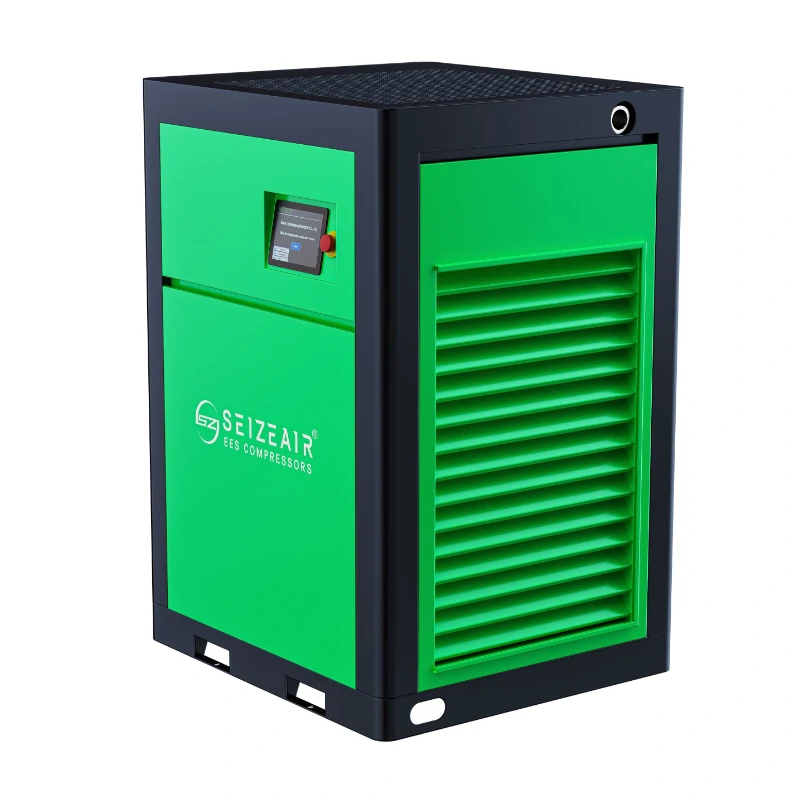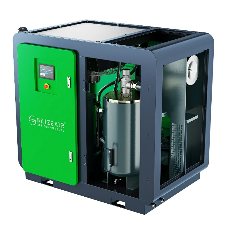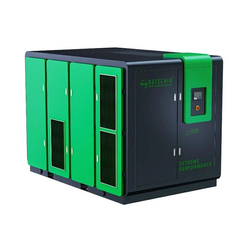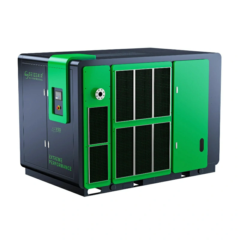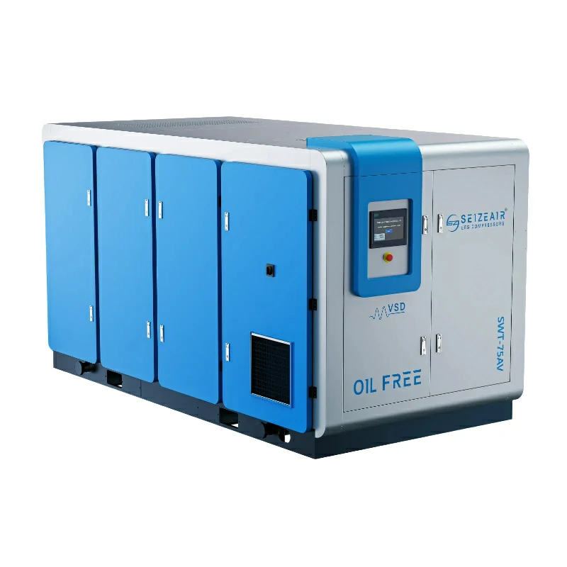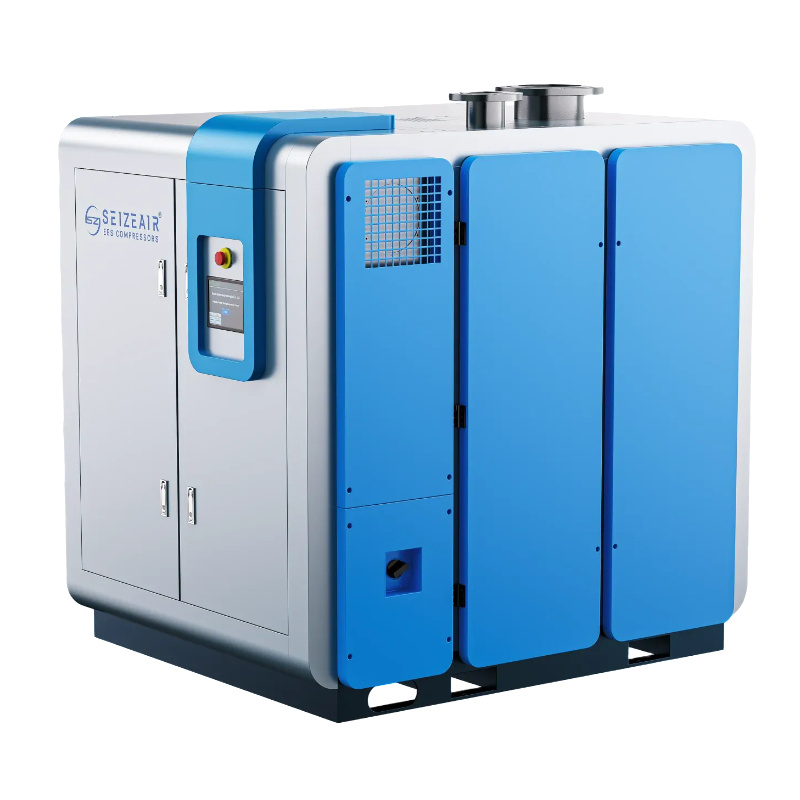


An air compressor for cement plant duty is a production machine, not a utility afterthought: it feeds baghouse pulse jets, conveying lines, kiln instruments and packing machines around the clock while inhaling hot, dust-laden air. This guide covers demand sizing, compressor selection, intake protection in a dusty plant, air treatment, ring-main losses, redundancy and the checks that belong in a purchase specification.
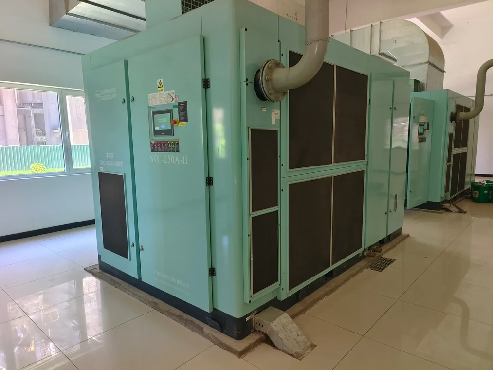
What Does Compressed Air Actually Do in a Cement Plant?
Start with the consumers, not with a catalogue. A cement works uses compressed air at several pressure levels and with very different cleanliness requirements, and most sizing mistakes happen because one number is written on a request for quotation before anyone walks the plant. Instrument air, pulse cleaning and conveying are three separate loads even when they share a header. Kiln and cooler areas also add heat and fine particulate that a general industrial compressor room never sees.
Instruments, actuators and kiln auxiliaries
Pneumatic actuators on dampers, diverter gates, burner controls and sample probes need clean, dry air at a stable pressure. A short pressure dip here can move a damper at the wrong moment, which is why instrument air is usually taken downstream of its own filter and regulator rather than straight off the main header. Valve positioners, solenoid banks and air sets each have a nameplate or a data sheet that states required supply pressure and air quality. Record those values before choosing a compressor, because the highest consumer in the plant sets the pressure band for everyone else.
Baghouse and dust collector pulse cleaning
Pulse-jet filters clean bags with short, repeated bursts of air from a header and diaphragm valves. The flow is intermittent, but the peak is sharp and the events keep coming all shift. A header that is too small, or a receiver too far from the valves, gives a weak pulse at the far end of the collector and the bags blind over. Count the valves, read the valve maker’s volume per pulse and the minimum supply pressure, then convert that into a peak flow at the receiver. This load should be treated as a transient demand superimposed on the steady plant load, not averaged away into a single mean figure.
Conveying, blending and silo aeration
Powder transfer, airslides, homogenising silos and some dense-phase systems need large volumes at comparatively low pressure. Running that duty from a 7–8 bar(g) plant-air header wastes the pressure drop twice: once at the compressor and again at the regulating valve. A dedicated low-pressure machine is often the cleaner answer. Seize Air supplies both magnetic levitation centrifugal blowers for silo aeration and oil-free screw blowers for low-pressure conveying, and the split between a blower and a compressor is one of the first decisions to make on a cement project.
Packing, loading and general plant air
Rotary packers, truck and wagon loading spouts, air cannons on build-up prone chutes, cleaning lances and workshop tools all draw from the same general network. These loads are scattered and poorly documented, which makes them the usual hiding place for leakage. Walk the lines with the plant running, mark every tee that feeds a consumer nobody can name, and put those points on the drawing before signing off a flow figure. Undocumented tees have a habit of becoming permanent leaks after a shutdown.
| Consumer group | Typical pressure band | Air quality concern | Load pattern |
|---|---|---|---|
| Instruments and actuators | Plant-air band, regulated locally | Dry, oil-free, particulate-free | Steady, small |
| Baghouse pulse jets | Plant-air band, verify against valve data | Dry; no condensate at the diaphragm | Short, repeated peaks |
| Conveying and silo aeration | Low-pressure band, separate machine | Clean; oil carryover harms powder | Long, near-continuous |
| Packing, loading, tools | Plant-air band | General purpose, filtered | Irregular, leak-prone |
The pressure bands in the table are deliberately descriptive. Valve, receiver and instrument nameplates on your own site overrule any general guide, and a supplier should ask for those drawings rather than fill them in for you.
How Do You Size an Air Compressor for Cement Plant Demand?
Sizing is an audit with four outputs: a normal flow, a peak flow, a pressure band at the farthest consumer, and a duty profile. Those four numbers decide the machine count, the control strategy and the receiver volume. Skip any of them and the station will either short-cycle at night or lose pressure during the morning peak.
Build the consumer list from nameplates
For each point of use, write down free air delivery, minimum supply pressure, duty cycle and whether the flow is continuous, intermittent or emergency-only. Convert every figure to one basis before adding them up: FAD at the site’s inlet conditions, Nm³/h, or cfm, but never a mixture. Manufacturers quote different reference conditions, and a number without its reference temperature and pressure is not a specification. Where a nameplate is missing, measure the flow or use a temporary logger on the branch instead of guessing from pipe diameter.
Add simultaneity, leakage and reserve
Not every consumer peaks at once, so a diversity factor is legitimate; a flat percentage applied without evidence is not. Derive it from the operating sequence of the kiln line and packers, then add measured leakage and a defined reserve for future points of use. Leakage is best measured during a planned stop with one compressor feeding the header, taking the flow needed to hold pressure. Write the arithmetic into the RFQ so the bidder can see which part is measured and which part is allowance.
Q_normal  = SUM(Q_i x D_i)
Q_design  = Q_normal + Q_leak + Q_reserve
Q_peak    = Q_design + Q_pulse_peak - Q_sheddable

P_set = P_critical + dP_pipe + dP_dryer + dP_filter + dP_margin

Q_i        = nameplate FAD of consumer i, one common reference basis
D_i        = diversity factor from the operating sequence
Q_leak     = measured flow needed to hold pressure at a plant stop
Q_pulse_peak = simultaneous baghouse valve demand at the receiver
Set pressure where the air is used
Work backwards from the most demanding consumer. Add the losses across dryers, filters, the ring main, isolation valves and the final hose, then set the compressor discharge accordingly. Raising the whole header to fix one remote pressure complaint is the most expensive form of troubleshooting, because every extra bar increases unregulated consumption and leakage across the entire network. Fix the local restriction first, then re-check the band. A plant pressure drop troubleshooting procedure helps separate a genuine capacity shortage from a blocked filter or a partly closed valve.
Turn the audit into a sizing sheet
One sheet should travel with the enquiry, the purchase order and the commissioning file. It lets the plant team, the EPC contractor and the compressor supplier argue about the same numbers. The sequence below is the one we use when an enquiry arrives with nothing but a motor power and a plant name.
Consumer list -> common flow basis -> diversity profile
       |
       +--> Q_normal, Q_peak, P_set, duty bands
                |
                +--> machine count + control mode + receiver
                          |
                          +--> RFQ, FAT, site acceptance test
| Line item | Source of the value | Who confirms it |
|---|---|---|
| Each consumer FAD and minimum pressure | Nameplate or OEM data sheet | Plant instrumentation team |
| Diversity and shift pattern | Operating sequence, historian trends | Production / process engineer |
| Leakage allowance | Measured at a planned stop | Maintenance team |
| Reserve for future consumers | Plant expansion plan | Project owner |
| Allowable losses across treatment | Dryer and filter data sheets | Supplier, in writing |
Which Compressor Type Fits a Cement Plant Best?
There is no single best machine for a whole cement works. A sensible station separates the steady base load from the shifting load, and separates high-pressure plant air from low-pressure process air. Once those two splits are drawn, the choice becomes a short list rather than a catalogue search.
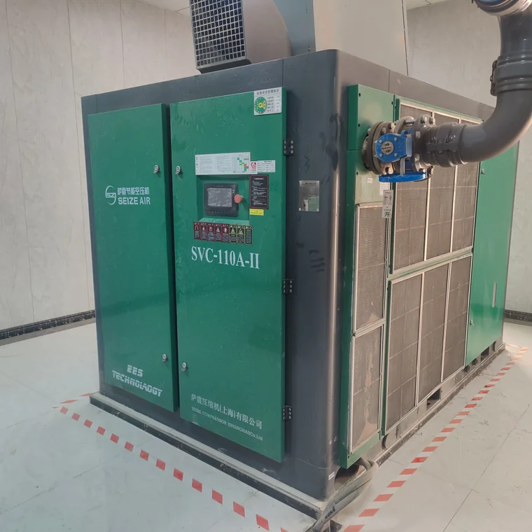
Oil-injected single-stage screw packages
For general plant air in the common 7–8 bar(g) band, an oil-injected rotary screw remains the default: packaged, air- or water-cooled, straightforward to service, and available across a wide power range. It handles continuous duty well when the cooling air is clean and the enclosure is not boxed into a hot corner. The trade-off is that oil carryover must be managed downstream, so filtration belongs in the specification rather than being added after the first complaint from the packing line. A full range of oil-injected screw compressors covers this duty, with the exact model chosen against the sizing sheet above.
Two-stage compression for the steady base load
When a compressor runs near full load for most of the year, the extra cost of a two-stage airend is worth examining. Splitting the pressure rise across two stages with intercooling reduces the work of compression and lowers discharge temperature, which is useful in a plant where ambient temperature around the kiln line is already high. The two-stage oil-injected screw compressor range is intended for exactly this kind of long, steady base-load shift. Ask for specific power at your own discharge pressure and inlet conditions, not a headline percentage, and compare it at the same duty point as the single-stage offer.
Variable speed for the shifting load
Packing, loading and shift-change patterns move the demand curve up and down. A fixed-speed machine answers that by loading and unloading, and every unloaded minute still consumes power. A permanent magnet variable speed package trims motor speed to follow the header instead, which is why VSD units are normally assigned the trim role while fixed-speed machines carry the base. The permanent magnet variable speed screw compressor is the usual candidate; our separate explanation of variable speed drive technology sets out where the savings do and do not appear. Check the turndown range against your measured night load before assuming one machine can cover both extremes.
Gear centrifugal for large, steady flow
Big integrated lines with a large, flat air demand can justify a centrifugal machine. The gear centrifugal series published in the 2026.08 English catalogue covers 1.5–16 barG and 40–380 m³/min, with API 672 and AGMA Q4 balance requirements noted in the same document; those are series-level figures, so the actual model table and the site’s inlet conditions decide the final selection. Centrifugal machines dislike a rapidly changing demand and need their surge control respected. The gear centrifugal air compressor series belongs in the comparison when the load stays high and steady, not when it swings with a packing shift.
Keep low-pressure process air separate
Silo aeration, airslides and homogenising do not need plant-air pressure. The 2025-10 English magnetic levitation blower catalogue lists 22–400 kW at 0.3–1.2 bar, while the oil-free screw blower catalogue lists 22–250 kW at 0.4–2.0 bar, both quoted at stated inlet conditions. Treating either as a compressor, or throttling an 8 bar machine down to feed them, blurs two different specifications. Put the low-pressure consumers on their own line with their own controls and their own acceptance test.
| Machine | Role in a cement works | Check before specifying |
|---|---|---|
| Single-stage oil-injected screw | General plant air, flexible duty | Downstream filtration and cooling air quality |
| Two-stage oil-injected screw | Steady base load, long running hours | Specific power at the site duty point |
| PM variable speed screw | Trim machine for a shifting load | Turndown range versus measured night load |
| Gear centrifugal | Large, flat, continuous flow | Surge control and inlet conditions |
| Low-pressure blower | Silo aeration, airslides, conveying | Separate header; no throttling from plant air |
Do Cement Plants Need Oil-Free Compressed Air?
Sometimes, but not everywhere. The answer depends on where the air goes. Air that touches powder, product-contact surfaces or sensitive instruments carries a different risk from air that drives a workshop tool or a damper actuator. Splitting the network by risk is cheaper than declaring the whole station Class 0.
Where oil carryover actually matters
Conveying air enters the powder stream, so oil aerosol can end up in the product. Pulse air reaches filter media, where oil and water together cake the bags. Instrument air reaches small orifices and positioners that tolerate neither. Those three branches justify either a genuinely oil-free machine or a properly specified multi-stage filtration train with monitoring. General plant air, cleaning lances and most actuator supplies can stay on a well-filtered oil-injected system. Write the branch requirements into the piping and instrumentation diagram, because a filter installed in the wrong place protects nobody.
What Class 0 certification does and does not cover
Air purity is described by ISO 8573-1 classes for particles, water and oil; an oil-injected machine with good filtration is still a different claim from a certified oil-free airend. Seize Air holds GC Class 0 certificates for the dry oil-free screw range (certificate 08823P10001) and the water-lubricated screw range (GC24009009000223), issued against ISO 8573-1:2010, ISO 8573-2:2018 and ISO 8573-5:2001 and valid to 2028-01-04. Coverage is limited to the models listed on each certificate, so a model outside that list is not covered by inference. The dry oil-free screw air compressor range is the relevant product family when a cement plant specifies a Class 0 branch.
Specify the test point, not just the label
A purity class is meaningful only at a stated sampling point under stated conditions. Ask bidders to identify where oil, water and particles are measured, which test methods apply, and who records the result at commissioning. For instrument air, specify the pressure dew point at the driest season condition the site actually sees, then verify it with a logged instrument rather than a one-off reading. For conveying, agree on the sampling method with the quality laboratory before the acceptance test. Neither conversation belongs at the end of a project, when the pipework is already welded.
How Does Cement Dust Change the Installation?
Cement dust is fine, alkaline and abrasive. It loads intake filters, insulates cooler surfaces, finds its way into cabinet electronics and turns condensate into sludge. A compressor room that would be acceptable in a machine shop will need attention here long before its first scheduled service.
Put the intake where the air is cleanest
Air intake should be drawn from the cleanest available side of the building, away from kiln exhaust, clinker cooler discharge, baghouse outlets, truck routes and any pile of raw meal. Where that is impossible, duct the intake to a higher, cleaner level and size the duct so the machine is not starved. Keep the room under slight positive pressure with filtered make-up air so dust is not pulled through door gaps every time a panel is opened. The 2021 English oil-injected operation manual lists an installation envelope of −5 to +40 °C, relative humidity below 85 %, altitude below 1000 m and duct air velocity below 4 m/s; that is the envelope of that manual edition, not a blanket claim for every current model, so the latest installation instructions for the ordered machine govern.
Protect the cooling path
Cooling air has to enter low and leave high without recirculating back into the same enclosure. Short, straight discharge ducts with flexible connectors cost less than a high-temperature trip during a summer kiln campaign, and the duct should never become the plant’s convenience shelf for spare bags. Air-cooled machines reject a lot of heat into a small room; water-cooled machines move the problem to the water circuit, which then needs its own water quality and flow monitoring. Either way, record inlet and outlet temperatures at full load during commissioning, then repeat the measurement in the hottest month. A rising trend is a filter or fan problem long before it becomes a motor problem.
Keep the cabinet sealed and the floor dry
Dust on a variable frequency drive heatsink is an electrical fault waiting for a humid shutdown. Specify cabinet sealing, filtered cabinet ventilation where applicable, and a cleaning routine that uses a vacuum rather than compressed air blowing dust further into the electronics. Condensate drains discharge into a visible, trapped drain, never onto the floor beside a steel base frame. Oil and cement dust together form a paste that hides corrosion, so housekeeping belongs in the maintenance checklist with the same status as filter changes.
Plan from site conditions, not from a brochure
Altitude, ambient temperature and inlet air density change the delivered mass flow of any compressor. A plant on a high plateau in a hot season should give the supplier the actual site conditions and ask for the guaranteed FAD at those conditions. That single line in the specification prevents an argument at the acceptance test. Ask also for the derating method in writing, and for the spare filter strategy: a two-stage intake filtration arrangement with a differential pressure indicator costs little and turns an invisible restriction into a scheduled task.
What Air Treatment Does a Cement Plant Need?
Treatment is chosen for the most sensitive branch, then applied where it is needed. Drying, filtration and storage each solve a different problem, and their order in the pipework matters more than the brand on the housing.
Drying: set the dew point from the coldest pipe
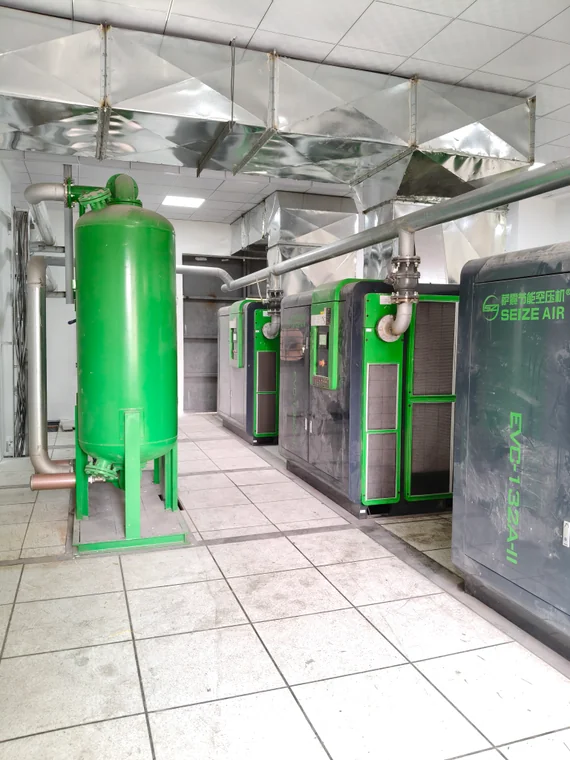
Water condenses wherever the compressed air cools below its pressure dew point. In a cement works, long outdoor headers and cold silo pipework are exactly those places, and moisture at a baghouse diaphragm or an airslide is a process problem, not a comfort issue. A refrigerated dryer in air-cooled or water-cooled form suits most general plant branches, provided the lowest expected pipe temperature stays above the achievable dew point. Where lines run outdoors in a cold season or instruments are sensitive, the no-heat or low-heat adsorption dryer range is the more appropriate choice. State the required pressure dew point at a defined location, then log it.
Filtration: coarse to fine, in the right order
A coalescing filter before a dryer is a different component from a particulate filter after one. Put general-purpose pre-filtration ahead of the dryer to protect it, a coalescing stage where oil aerosol must be removed, and a dry particulate stage downstream for dust and desiccant fines. Each housing needs a differential pressure gauge and a drain that actually works. In a dusty plant, intake filtration is the first stage of the whole chain; skipping it simply moves the dirt into the compressor oil and then into the downstream elements. Record element change dates and pressure drops together, because a shortened interval is the clearest evidence that the room is being contaminated.
Storage: the buffer for pulse jets
A receiver placed close to a baghouse header decouples short, sharp pulses from the compressor control loop. A receiver placed only at the compressor house leaves the far end of the collector starved. Size the buffer from the allowable pressure band at the valves and the duration of the pulse event, then confirm the vessel’s design pressure, certification and drain arrangement for the local jurisdiction. Wet receivers need an automatic drain with a bypass and a visible discharge point; a manual drain on a remote vessel is a task that will eventually be forgotten. Isolation valves and a safe depressurising route belong on the drawing as well.
How Much Pressure Drop Is Acceptable in the Plant Ring?
Pressure drop is a design variable, not a fate. Every fitting, undersized pipe, half-closed valve, clogged filter and long small-bore hose consumes part of the pressure you paid for at the compressor. In an old cement works, the ring main is often the single largest avoidable loss on the whole system.
Measure before you replace
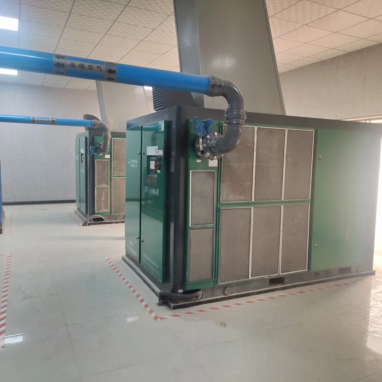
Put gauges or loggers at the compressor discharge, after the treatment train, at the ring’s far end and at the critical consumer. The difference between those readings splits the total loss into treatment losses, distribution losses and local losses. A large drop across a dryer or filter usually means a service item; a large drop along the ring means velocity, length or a partly closed valve; a large drop across the last hose means a local fix. Only after that mapping does a capacity shortage become a credible diagnosis. Keep the readings from the same shift and the same production state, or the comparison will say more about the kiln than about the pipe.
A ring beats a dead-end tree
A closed loop fed from two directions halves the effective distance to any consumer and gives you an isolation path during maintenance. Take-offs come off the top of the header to keep condensate moving to the drop legs, and low points get drains. A simplified layout looks like this:
        [compressor house: dryers -> filters -> main receiver]
              |                                     |
              +=========== ring header =============+
              |         |         |        |       |
           baghouse   packing   kiln    silo     workshop
           (buffer)   (regulator) (F/R) (low-p)  (isolation)
              |         |         |        |
           drains at every low point, take-offs from the top
Leaks are a pressure problem too
An open blow-off or a failed drain wastes flow, and the controller responds by keeping an extra machine loaded. In a cement plant, leaks hide in pulse valve manifolds, quick couplings on cleaning lances and old underground sections. Walk the plant with an ultrasonic detector during a quiet shift, tag each find with an estimated size and a repair date, then repeat the survey after the shutdown. The comparison gives you a defensible leakage figure for the sizing sheet instead of a percentage copied from a handbook. Pressure band, leak load and machine sequencing should be reviewed together; changing one in isolation usually just moves the symptom.
How Do You Keep the Plant Running During Service or a Trip?
A kiln does not stop because a compressor is being serviced. Redundancy is therefore a process decision: which consumers must stay alive, for how long, and what the plant does while one machine is down. Answer those three questions and the number of machines follows.
Choose an N+1 arrangement deliberately
For a continuous line, the common choice is to carry the normal load on several machines with one spare of equal capacity, so any single unit can be isolated without losing the header. Splitting capacity across three or more machines also gives finer sequencing at low demand than one large trim machine plus one large base machine. Where the plant has separate high- and low-pressure networks, redundancy belongs on each network, not just on the biggest one. A standby unit that has never been rotated into service is not a standby unit; put it in the weekly sequence and log its running hours.
Isolate, bypass and label
Every machine, dryer, filter and receiver needs isolation valves on both sides, a safe depressurising route and a marked bypass where a treatment item can be serviced without killing the whole header. The bypass must be locked or procedurally controlled, otherwise it quietly becomes the normal operating path and the dryer is blamed for water in the lines. Number the valves on the piping diagram and physically on the plant. During a night-shift trip, nobody should have to trace a pipe to find which valve isolates a failed drain.
Prefabricated stations for brownfield sites
Many cement works have no spare indoor floor and no appetite for a long civil project. A containerized air compressor station arrives with the machines, treatment, piping, ventilation and electrical distribution already integrated and tested, so site work is largely foundation, power and air connections. Our separate skid-mounted station design and selection guide explains how that differs from a skid or a trailer, which matters when the plant is choosing between a permanent room and a relocatable package. Keep the dust and ventilation rules from the previous section even when the enclosure is supplied complete.
Spares that actually shorten a stoppage
Stock the items that stop you: intake filters, oil and separator elements, a condensate drain kit, critical sensors, and the drive belts or coupler components called out in the manual. Cement dust consumes intake elements faster than a clean factory, so set the initial stock from the site’s own differential-pressure trend rather than a generic list. Agree response times and exclusions in the contract for the country of installation; a domestic service promise does not automatically travel with an export order. Record every top-up so the next shutdown order is based on consumption, not memory.
What Should the Control System Log?
A compressor controller is the cheapest data logger on the site. If it records the right signals, most energy and reliability questions can be answered from history instead of from an argument.
Signals worth trending
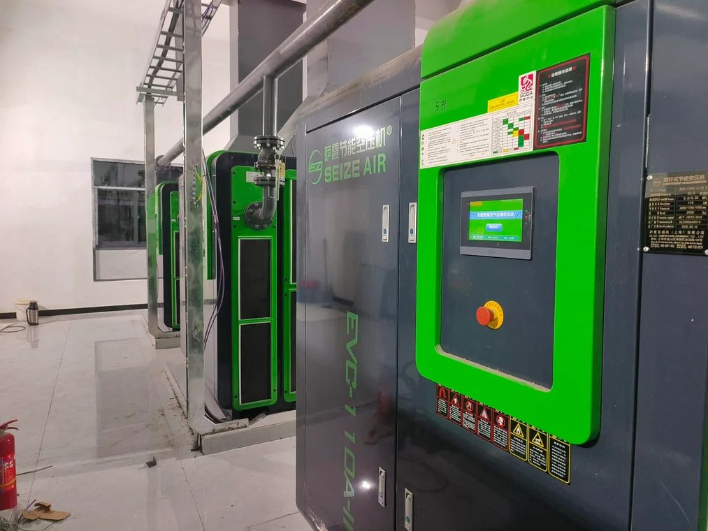
Log header pressure, individual machine load and unload state, running hours, motor current or input power, discharge temperature, intake filter differential pressure, dryer dew point and condensate drain events. Add ambient temperature at the intake if the room is hot. Pressure excursions should be correlated with production events such as baghouse cleaning cycles and packer starts, which is how a demand spike gets separated from a capacity problem. A month of trends at a one-minute interval is usually more useful than a year of daily averages, because the interesting events last seconds.
Sequencing and alarms
Multi-machine control should rotate lead and trim roles to even out hours, hold a tight pressure band, and shed non-critical consumers in a defined order when pressure falls. Agree that order with production: a cleaning lance can be shed, an instrument air branch cannot. Alarms go to the control room, not only to a panel in an unstaffed compressor house. Where a plant historian exists, expose the same signals over a standard protocol so maintenance and production look at one version of the truth. Test the changeover sequence during commissioning with one machine deliberately stopped.
How Do You Estimate Energy Cost Without Guessing?
Compressed air is usually one of the larger electrical loads in a cement works, but the number belongs to your plant, not to a brochure. The calculation is simple; the inputs must be measured.
Use specific power at the right duty point
Specific power is input power divided by delivered free air, and it is only comparable when the discharge pressure, inlet conditions and test method are the same. Ask for the figure at your own duty point with the test standard named, and check whether it is motor rated power, package input power or shaft power: those are three different numbers and mixing them flatters whichever offer was prepared loosest. The Compressed Air and Gas Institute data sheet guidance is a useful reference for reading performance claims. A witnessed test report is evidence about the tested unit, not a guarantee for a whole series, so confirm the model and conditions on the actual certificate.
Build the cost from site measurements
Read running hours from the controller, input power from a meter, load factor from the trend, and the tariff from the site electricity invoice. Do not substitute an assumed tariff, an assumed number of shifts or a published national average for those four inputs; the plant is buying its own bill, not an industry average. Once the baseline exists, the same formula prices a VSD, a leak repair programme or a new ring main on equal terms.
E_kWh   = P_input(kW) x t(h) x LF
SEC     = P_input(kW) / Q_FAD(m3/min)
Cost    = E_kWh x tariff_from_site_invoice

LF      = loaded fraction from the controller trend
t       = measured running hours, not calendar hours
Q_FAD   = measured or guaranteed delivery at stated inlet conditions
Put the whole life cost on one page
Purchase price is a small part of the comparison across a long-running cement asset. Energy, planned service, filter and oil consumption, unplanned downtime, spare parts logistics and the cost of a pressure dip at the kiln all belong in the same table. Industry context on cement production and energy use is available from the Portland Cement Association resources; the plant’s own meter remains the authority for its own numbers. Ask bidders to state service intervals in operating hours and to list consumables by part number, so the comparison survives a change of procurement staff.
What Belongs in Installation and Commissioning?
Commissioning is where the sizing sheet is either confirmed or quietly abandoned. Treat it as a measurement exercise with a signed record, not as a start-up button.
Before energising
Verify the foundation, levelling, flexible connections and anchoring; confirm that intake and discharge ducts are independent and unobstructed; check rotation, oil level, electrical protection settings and earthing; walk the pipework against the final isometric. Flush and blow the header before connecting sensitive instruments, because construction debris in a new ring main finds the smallest orifice available. Confirm that pressure relief devices and receiver certification match the design pressure and local rules. Assign a single person to sign off each item.
During the acceptance test
Record FAD or a proxy flow measurement, discharge pressure at the compressor and at the farthest consumer, input power, ambient and intake temperature, pressure dew point, filter differential pressures and the controller’s load and unload pattern. Run the baghouse pulse sequence at its real rate while logging header pressure at the valve manifold. Repeat the test in the hot part of the day if the room is exposed. File the results with the sizing sheet: a year later, that sheet is the only way to tell degradation from an underspecified original design.
What Does a Dusty-Duty Maintenance Schedule Look Like?
Cement plants do not need an exotic maintenance philosophy; they need short intervals, honest records and a room that stays clean. The schedule below is a framework. Every timed interval should be replaced by the value in the manual delivered with the ordered machine.
| When | Check | Evidence to record |
|---|---|---|
| Each shift | Header pressure, condensate drains, unusual noise, cabinet temperature | Shift log and any alarm list |
| Weekly | Intake filter differential pressure, cooler surfaces, room dust, oil level | Gauge reading with date |
| Monthly | Leak walk, dryer dew point, drain function, sequence changeover test | Tagged leak list and trend export |
| Per OEM manual, in operating hours | Oil, separator, coalescing and particulate elements | Part numbers and hours at change |
| Each planned kiln stop | Receiver inspection, safety valve function, header drains, leak repair | Signed inspection sheet |
Read the trend, not only the interval
A rising filter differential pressure after a kiln campaign tells you where dust is entering the room, and a falling dew point margin tells you a dryer is losing capacity before anyone sees water. Keep both on the same trend as production rate. Shortened element life is a design input for the next intake upgrade, not a reason to accept consumable cost as fixed. Where two identical machines in the same room age differently, look at their positions relative to the door and the discharge duct first.
Keep a shutdown task list
A kiln stop is the only chance to open a receiver, replace a buried section of the ring, or re-route an intake duct. Prepare the list a month ahead with parts, permits and isolation drawings attached. Compressed air work during a short stop competes with every other trade on site, and the jobs that were specified last are the ones that get deferred to the next stop. Log what was completed and carry the rest forward with a named owner.
What Should the Purchase Specification Ask For?
A good RFQ makes competing offers comparable and gives the commissioning team something to test against. It also filters out suppliers who would rather discuss motor power than delivered air.
- Site conditions: altitude, minimum and maximum ambient temperature, humidity, inlet air quality and available cooling water.
- Demand data: Q_normal, Q_peak, allowed pressure band at the farthest consumer, duty profile and measured leakage.
- Guaranteed FAD and specific input power at the stated duty point, with the test standard and inlet conditions named.
- Machine count and control strategy: base, trim, standby, sequencing, load shedding and communications protocol.
- Air treatment: pressure dew point at a defined point, filtration stages, receiver location and drain arrangement.
- Installation envelope: room layout, ducting, positive-pressure ventilation, cable routing and lifting access.
- Documentation: drawings, manuals in the required language, certificates with model coverage, spare parts list by part number.
- Acceptance test: who measures, with which instruments, over how long, and what constitutes a pass.
- Service terms for the country of installation: intervals, response arrangements, exclusions, training and warranty scope.
Ask every bidder to fill in the same sizing sheet. Blank cells are information, too: they show where a supplier is assuming instead of calculating. Price the offers only after the technical sheets line up, because a low bid built on a smaller FAD is not a lower price for the same air.
Frequently Asked Questions
What size air compressor does a cement plant need?
There is no honest plant-wide rule of thumb. Size from a consumer list using nameplate FAD on one common reference basis, apply a diversity factor derived from the operating sequence, then add measured leakage and a defined reserve. Check the result against the baghouse pulse peak, which is a short-duration load that a daily average hides. A supplier who quotes a kilowatt figure before seeing the demand sheet is guessing.
What pressure do cement plant baghouses use?
Pulse-jet collectors are normally fed from the plant-air header, but the required supply pressure at the diaphragm valves comes from the valve and filter media data sheet, not from a general guide. Confirm that value, add the losses between the receiver and the farthest valve, and place a buffer vessel near the collector. Test at the real pulse rate; a static pressure reading taken between pulses says nothing about the dip during cleaning.
Screw or centrifugal: which is better for a cement plant?
It depends on the shape of the load. Oil-injected screw packages cover the common plant-air band and tolerate changing demand, especially with a variable speed trim machine. Gear centrifugal machines suit a large, steady, flat flow and need their surge control respected. Many works end up with screw machines for plant air plus a separate low-pressure blower for silo aeration, because one machine cannot serve both pressure bands efficiently.
Can one compressor serve the whole plant?
Technically yes, operationally no. One machine gives no maintenance window, no redundancy and poor part-load behaviour when the packing lines stop. A kiln line runs continuously, so an N+1 arrangement with rotated lead and trim roles is the normal choice. Separate the low-pressure consumers onto their own machine at the same time, otherwise the single unit would have to be throttled for most of its duty.
How often should intake filters be changed in a cement plant?
Change on differential pressure and on the trend, not on a fixed calendar copied from a clean factory. Cement dust loads elements far faster, and the rate changes between a normal campaign and a period of heavy haul-road traffic. Fit a differential indicator, record it weekly, and use the first few months of data to set the site’s own interval. A shortened element life usually points to an intake location or room-sealing problem worth fixing.
Is oil-free air required for cement conveying?
Where air contacts powder directly, oil aerosol is a product-quality risk, so either a certified oil-free airend or a monitored filtration train with a defined test point belongs in the specification. Instrument air and baghouse pulse air also deserve a clean, dry branch. General plant air and workshop tools do not automatically need Class 0. Splitting the network by risk is usually more economical than certifying the whole station.
How do I stop pressure dips during pulse-jet cleaning?
First measure the dip at the valve manifold with the real pulse sequence running. Then work outward: receiver volume and location, header diameter, isolation valves, filter differential pressure and finally compressor sequencing. A local buffer close to the collector often solves what looks like a capacity shortage. Only after those checks does adding another machine make sense, and the controller should shed non-critical loads before pressure reaches the instrument air branch.
Bringing the Specification Together
An air compressor for cement plant service should be bought against a measured demand sheet, a stated pressure band at the farthest consumer, an honest dust and ventilation plan, and an acceptance test that repeats the real pulse sequence. Get those four things right and the choice between screw, two-stage, VSD and centrifugal becomes a straightforward comparison. Seize Air can review a plant’s consumer list and duty profile and return a station proposal with the sizing arithmetic attached; send the plant data through our contact page and the technical team will work from your numbers rather than a catalogue estimate.