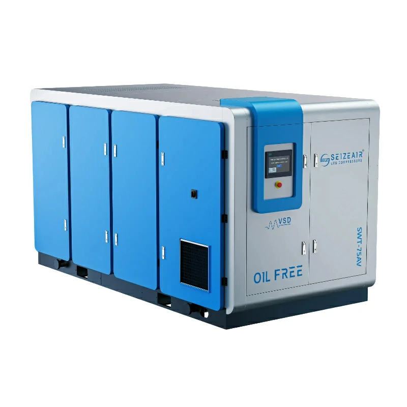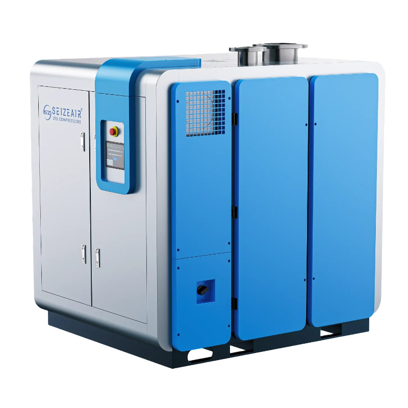


Compressed air pressure drop is the pressure lost as air flows through treatment equipment, distribution pipes and connections before reaching a machine. Diagnose it by comparing synchronized pressure readings during actual production. Identify where the loss develops, correct the restriction or supply problem, and verify the result before increasing compressor discharge pressure.
A machine that stops on low pressure does not automatically need a larger compressor. Its hose, regulator, filter or supply branch may limit flow even while the main header remains stable. Conversely, a falling pressure across the whole plant can indicate that available supply and demand are out of balance. Those situations call for different corrective actions.
This guide gives maintenance teams, plant engineers and industrial buyers a practical way to investigate unstable pressure. It covers measurement planning, fault patterns, treatment equipment, piping, controls and purchasing information. The aim is a documented decision about the complete air system, supported by operating evidence and the requirements of the affected production equipment.
What compressed air pressure drop tells you
Separate pressure from air delivery
Pressure describes the condition at a measurement point. Flow describes how much air moves through the system over time. A pipe can show a satisfactory pressure when a machine is idle, then deliver inadequate pressure when that machine starts consuming air. The idle reading alone cannot establish whether the connection can support the process.
Start with the equipment supplier’s required inlet conditions. Establish where that requirement applies: upstream of a regulator, at the machine connection, or inside a particular pneumatic circuit. Include the machine’s demand pattern and its air quality requirement. A comparison becomes useful only when the measurement location corresponds to the operating requirement.
If the plant is also selecting new generation equipment, use the separate screw compressor sizing guide as background. This pressure investigation focuses on locating losses and disturbances between generation and the actual user.
Distinguish a restriction from a supply shortage
A restriction creates a difference between an upstream and downstream pressure while air flows through the affected section. A supply shortage can pull both locations downward together. In practice, the two conditions may overlap, so an investigation should examine the relationship between readings rather than assign a cause from one gauge.
Record whether the station outlet remains steady when the machine inlet falls. Then compare intermediate locations along the supply path. A localized difference directs attention to components within that section. A broad decline requires a review of compressor availability, demand, storage and control response.
Describe the observation in plain terms on the work order. For example, write that the header remained stable while the machine inlet declined during a specific operating sequence. Avoid recording an unproven diagnosis such as insufficient compressor capacity before the measurements support it.
Keep air quality and pressure together
Removing filtration or bypassing a dryer may alter pressure readings, but it can also expose the process to unsuitable air. The pressure requirement and the cleanliness requirement belong in the same investigation. Production acceptance must address both.
Ask the process owner to identify the applicable quality specification and the point where it must be met. Preserve any validated arrangement used for sensitive manufacturing. Changes to treatment equipment should involve the relevant quality or engineering team before implementation.
The solution may be a correctly sized treatment component, a maintained filter element or a revised distribution arrangement. A pressure improvement is incomplete if it causes moisture, oil or particles to reach equipment that cannot tolerate them.
Build a compressed air pressure drop measurement plan
Draw the actual supply path
Trace air from the compressor station to the affected process. Include receivers, dryers, filters, isolation valves, main pipes, branch pipes, regulators, hoses and quick couplings. Mark which components are shared with other production areas and which belong only to the problem machine.
Use the installed arrangement as the basis of the drawing. Older plans may omit a recently added filter or show a valve position that no longer reflects operation. Confirm uncertain details with maintenance staff and a physical inspection carried out under the site’s access procedures.
A simple diagram is sufficient when it accurately describes the path. Give each measurement point a clear location name. The objective is to let another engineer understand the readings without having to reconstruct where each gauge was connected.
Select useful measurement locations
Useful points often include the station’s treated-air outlet, the supply to the affected production area, and the machine inlet. Add upstream and downstream points around a suspected restriction. Available approved test ports should determine the practical arrangement.
Check whether the compressor display represents an internal sensor or the actual station outlet. Air treatment and package components can lie between that sensor and the distribution system. A reading at the controller should therefore carry a location description rather than be labelled simply as plant pressure.
Choose instruments appropriate to the expected conditions and the event being investigated. Confirm calibration status and pressure rating. Installation, isolation and removal should follow site procedures and equipment instructions; do not loosen pressurized fittings to improvise a test point.
Measure during the reported operating event
Arrange the investigation around the production sequence that causes the complaint. A steady idle condition may conceal the problem. Ask operators whether the event occurs during startup, tool changes, packaging cycles, material transfer or simultaneous operation of several machines.
Record the relevant machine states alongside the pressure readings. Include compressor running status, maintenance activity and any unusual process demand. This operating context helps distinguish a repeatable process event from an isolated reading taken under different conditions.
Where the disturbance is brief, use a recording method capable of capturing its timing. A slowly observed gauge can miss a short pressure dip. Select the recording interval with the engineer responsible for the investigation rather than treating a convenient logging setting as adequate.
Synchronize and label the observations
Upstream and downstream readings must describe the same operating event. Separate measurements taken during different demand conditions can create an apparent loss that did not exist at either moment. Synchronize the instruments or record the time clearly enough to align their results.
Use consistent units and identify whether values are gauge or absolute pressure. Record the instrument, location and production condition with each dataset. If instruments disagree when exposed to the same reference condition, resolve that issue before interpreting a small difference between plant locations.
For a defined section, the basic relationship is pressure difference = upstream pressure minus downstream pressure. The arithmetic is simple. Its usefulness depends on comparable measurement conditions and a clearly identified supply path.
Read compressed air pressure drop patterns before choosing a repair
Stable header and falling machine pressure
This pattern points the investigation toward the branch and point-of-use components. Review the local supply route, then compare readings around the filter, regulator, hose and coupling. Check whether the problem began after a component replacement or a change to the machine’s operating sequence.
A physically compatible connection can still have unsuitable flow characteristics. The external thread size or hose appearance does not establish how it performs under demand. Obtain the component’s relevant flow information and compare it with the process requirement.
After identifying a likely component, confirm the diagnosis through a controlled correction and repeat measurement. Keep the rest of the operating conditions comparable. Replacing several parts at once can restore production while leaving the underlying cause uncertain.
Pressure falls throughout the plant
If the station outlet and several production areas decline together, review available supply and the combined demand profile. Check for a compressor that is unavailable, an operating fault, a change in sequencing or a newly added production load. Consider uncontrolled air consumption as well.
Compare the event with the station’s operating records. Look for changes in which machines are loaded, whether a standby unit starts as intended, and whether an alarm interrupts delivery. Review the complete control arrangement with qualified personnel before changing settings.
A plant-wide disturbance can justify a capacity assessment, but it does not establish the answer by itself. The purchasing decision still needs measured demand, required pressure, treatment performance and operating conditions. Record what the current equipment actually does during the event.
Pressure dips only during a short demand burst
A brief disturbance needs investigation of the demand event, the supply path and the system’s response. Identify the process that starts at the same time as the dip. Determine whether its operation changed or whether several intermittent users now overlap.
Storage and control arrangements may be relevant, but they should be assessed as part of the measured system. Adding a receiver without understanding the restriction or recharge conditions can leave the process with the same recurring problem.
Ask the system engineer to evaluate the event duration, required inlet condition and recovery behaviour. The decision should explain how the proposed arrangement supplies the event and recovers afterward. It should also address pressure-vessel requirements and the practical location of any additional equipment.
Pressure deteriorates after maintenance or expansion
Recent changes provide a useful starting point. Inspect replacement elements, valve positions, hose routing and newly installed treatment equipment. Verify that the intended component was fitted and that its direction of flow agrees with the manufacturer’s instructions.
For a plant expansion, check whether the new demand passes through a shared component that was selected for the previous installation. A branch extension can also alter how existing users interact. Update the system drawing so the review reflects the new configuration.
Use maintenance and commissioning records to compare conditions before and after the change. Where reliable earlier measurements are unavailable, state that limitation. A clear record of the current problem is more useful than a confident claim about an undocumented baseline.
Check treatment equipment for compressed air pressure drop
Filters: compare performance under actual demand
Include filtration in the measurement plan when the pressure difference appears across the treatment train or local connection. Inspect the element condition and maintenance record using the component supplier’s instructions. Verify that the installed grade and housing match the specified process.
Ask for flow and differential-pressure information at the relevant operating conditions. Review our precision filter product page when preparing a filtration enquiry. A catalogue rating needs its reference conditions before it can be compared with plant performance. Replacement decisions should preserve the necessary filtration duty.
Keep evidence of the change: the previous element identification, the replacement identification, the measured pressure difference and the production condition. Use the air compressor maintenance guide to organize related maintenance records. This gives the next maintenance team a useful baseline and helps reveal whether the same issue returns unusually quickly.
Dryers: review the complete duty
A dryer belongs in a pressure investigation when the loss develops through its part of the supply path. Confirm the actual inlet conditions and the treatment requirement. Inspect its operating state, alarms and maintenance history with the responsible service team.
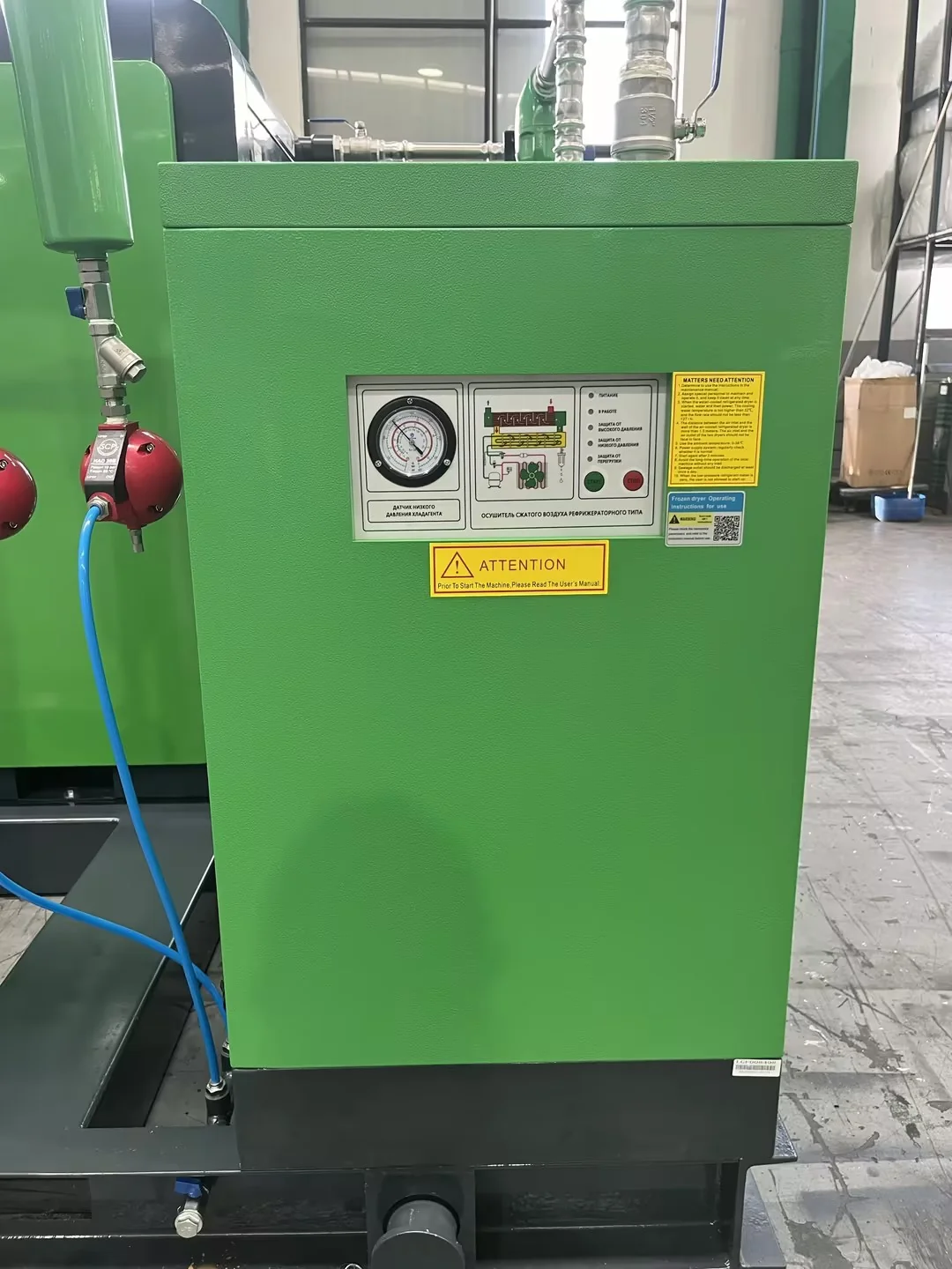
When requesting a replacement, provide more than nominal flow. The supplier needs the relevant inlet pressure, temperature, expected demand and required drying performance. Review the refrigerated air dryer product page when preparing the equipment scope. Those conditions determine whether the proposed unit is appropriate for the system.
Our refrigerated and desiccant dryer comparison provides related selection background. For the pressure investigation, keep the focus on measured behaviour through the installed equipment and the air quality the production process actually requires.
Regulators: inspect inlet and outlet together
A regulator setting describes an intended downstream condition. It does not prove that the condition is maintained during flow. Compare the inlet and outlet while the machine operates, and review the regulator’s performance information for that demand.
Check whether the upstream supply remains adequate during the event. A regulator cannot maintain an outlet condition that the incoming supply cannot support. Equally, a stable upstream reading does not establish that the selected regulator can pass the required flow.
Record any adjustment and repeat the operating sequence. Changes should remain within the machine’s approved inlet requirements. If the pressure behaviour remains unclear, consult the component and machine suppliers before substituting parts or altering the process setting.
Hoses, couplings and isolation valves
Follow the whole local connection, including any temporary hose, adapter or quick disconnect. Look for damaged routing, unnecessary length and components that were added for convenience during maintenance. Confirm that isolation valves intended to be open are in their correct operating position.
Obtain the appropriate flow characteristics for replacement components. Match the selection to the machine’s demand and operating conditions. A larger-looking component is not sufficient evidence that the connection has been properly specified.
After a correction, update the approved connection list or maintenance specification. Follow a model-specific spare parts identification process when requesting replacements. Otherwise, the next replacement may restore the original restriction. A simple record of the required component type and selection basis can prevent repeated troubleshooting of the same machine.
Review compressed air pressure drop in distribution piping
Trace the route and shared restrictions
Mark the main supply route, branch lengths, fittings and shared components on the system drawing. Identify where several production areas depend on the same pipe or valve. Compare pressure before and after that common section during combined operation.
Consider the installed internal condition and the suitability of the pipe material for compressed air service. An engineering assessment should address pressure rating, connections, support and compatibility with the environment. Existing outside dimensions alone do not describe the useful flow path.
When commissioning new distribution, include measurement access and practical isolation arrangements in the design. A network that is difficult to measure creates avoidable uncertainty later. Agree the locations with the engineer responsible for operating and maintaining the system.
Evaluate changes against a defined demand
A proposed pipe modification should state the demand and pressure conditions used in its assessment. Include current production and any approved expansion. Separate measured operating demand from an unconfirmed allowance for future equipment.
Ask the designer to explain which section is being changed and how the calculation relates to the recorded problem. A blanket recommendation to increase every pipe size can hide a restriction at a single valve or connection.
Agree how the result will be checked after installation. The acceptance method should include the affected process and representative simultaneous demand. Installation completion is an important milestone, but stable production performance provides the evidence that the modification addresses the complaint.
Use loops and alternative routes deliberately
A looped network or additional supply path can be considered during distribution design. Its value depends on the actual arrangement, flow sharing and isolation strategy. Treat it as an engineering option that requires assessment for the specific plant.
Describe how the modified network operates when a section is isolated for maintenance. Check which production areas remain connected and whether their supply still passes through an unintended restriction. The normal operating arrangement and the maintenance arrangement both matter.
CAGI compressed air guidance identifies piping and treatment restrictions as contributors to pressure loss. Use that system-wide perspective to structure the review, then base the final distribution design on the plant’s own conditions.
Connect compressed air pressure drop with control decisions
Identify what each controller measures
Map the pressure sensors used by individual compressors and any station controller. Record where they connect to the air system. A sensor upstream of a restriction may show a different condition from the production header it is expected to serve.
Review recorded operating states alongside the measured production event. Establish which unit is responding and whether another unit becomes available when required. This information can explain a disturbance without assuming that a particular control technology is at fault.
Control changes should be reviewed by people familiar with the equipment and system. Document the original settings, proposed change and acceptance conditions. Preserve any operating limits and interlocks specified for the installed machinery.
Assess fixed-speed and variable-speed roles
A variable-speed compressor can be evaluated for a changing demand profile. Its suitability depends on the selected equipment’s operating range and its relationship with the rest of the station. The presence of variable-speed control alone does not prove that every downstream machine receives stable pressure.
Likewise, fixed-speed equipment should be assessed within the actual duty and sequencing arrangement. Review load patterns, standby requirements and how available supply changes through the production day. Technology labels do not replace an operating record.
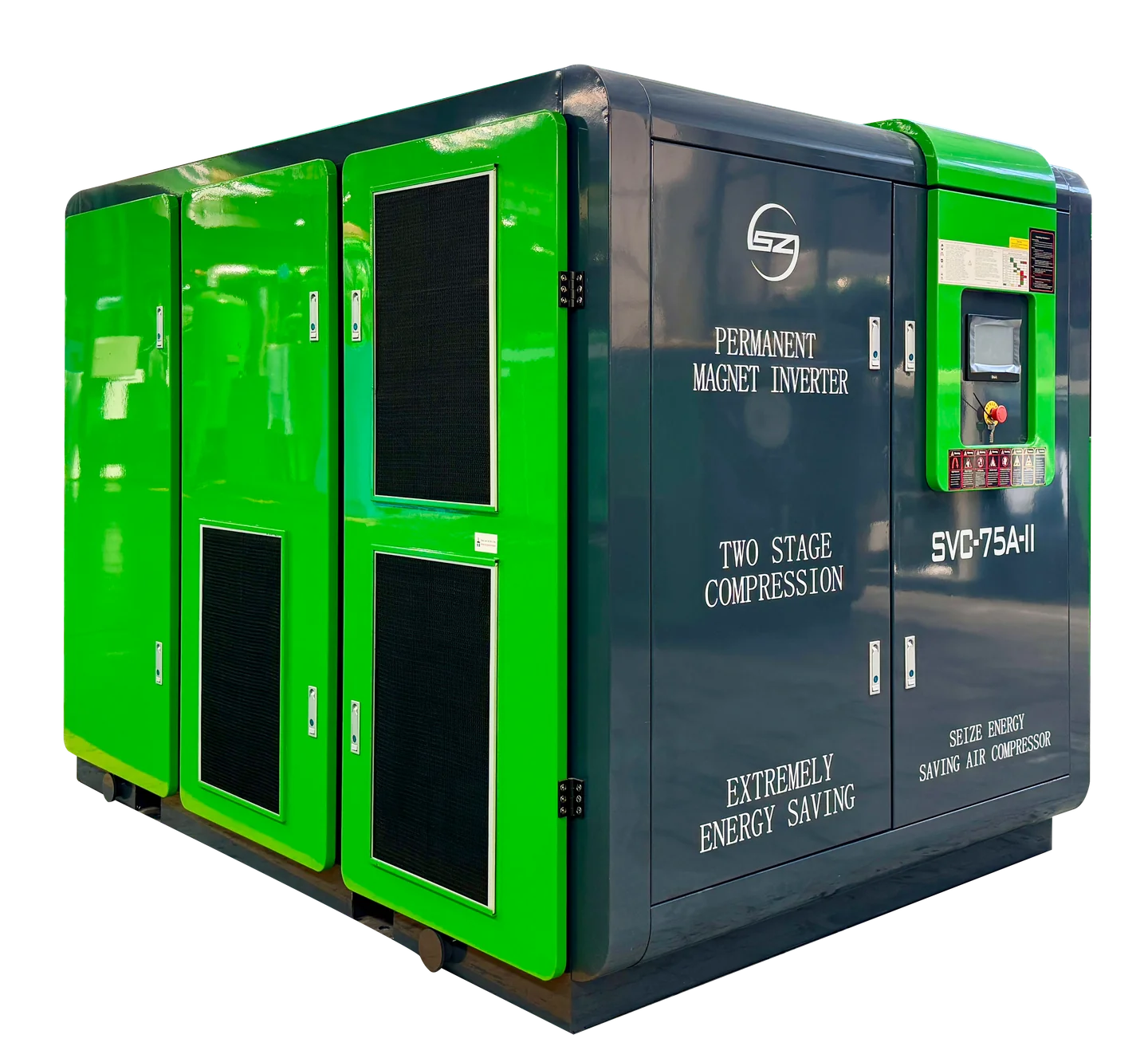
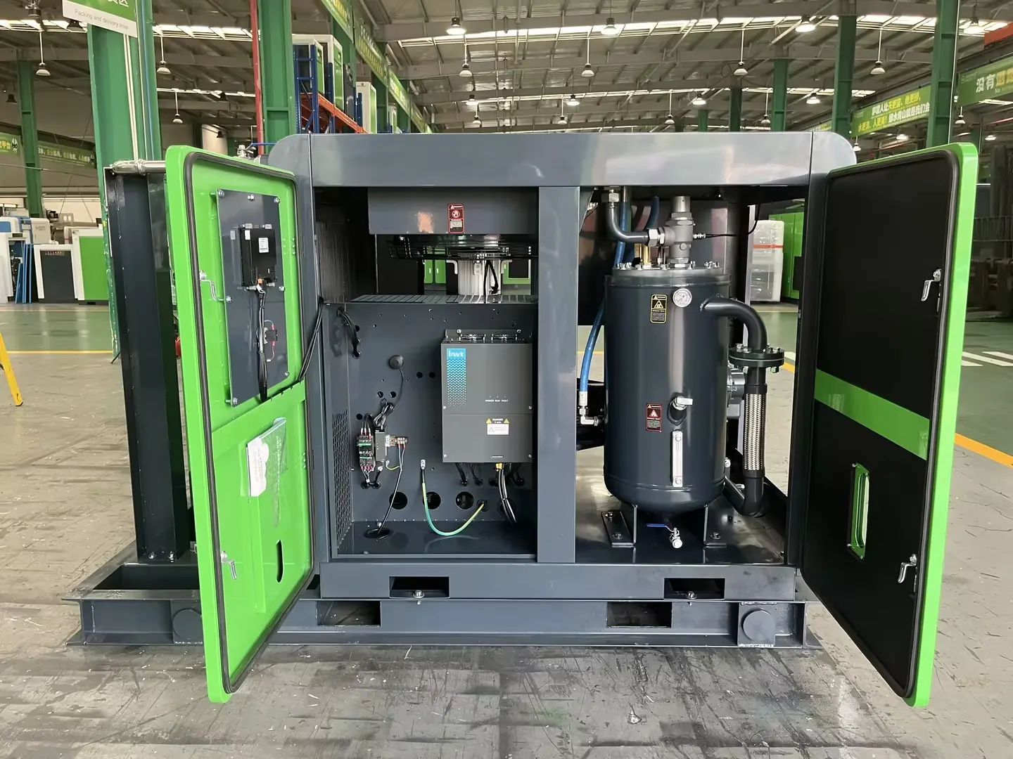
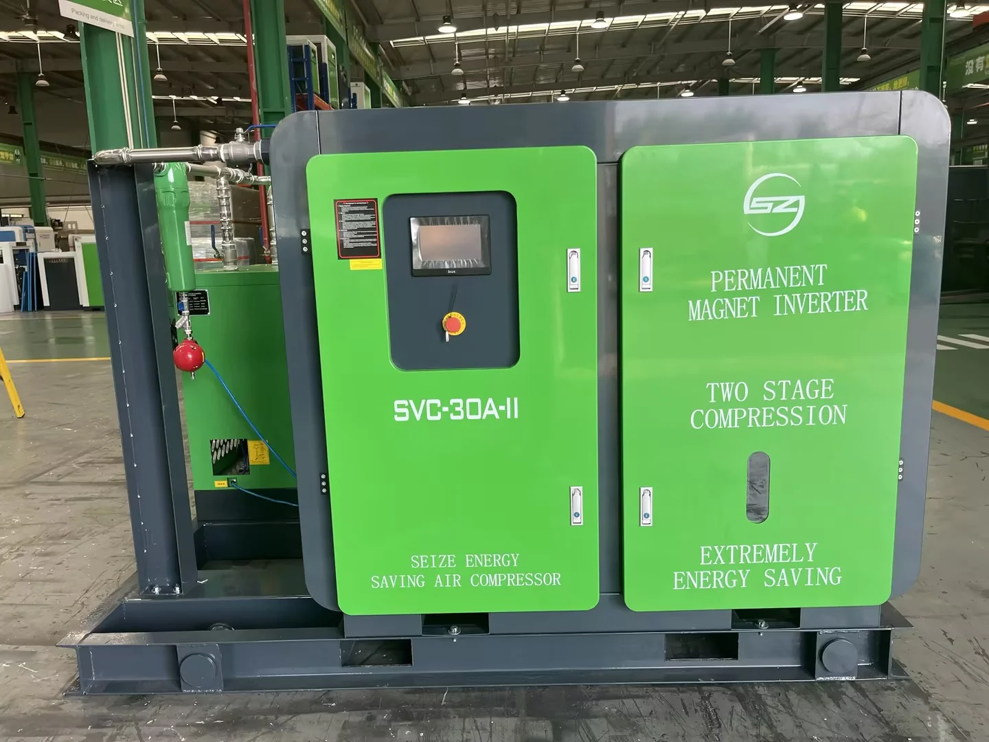
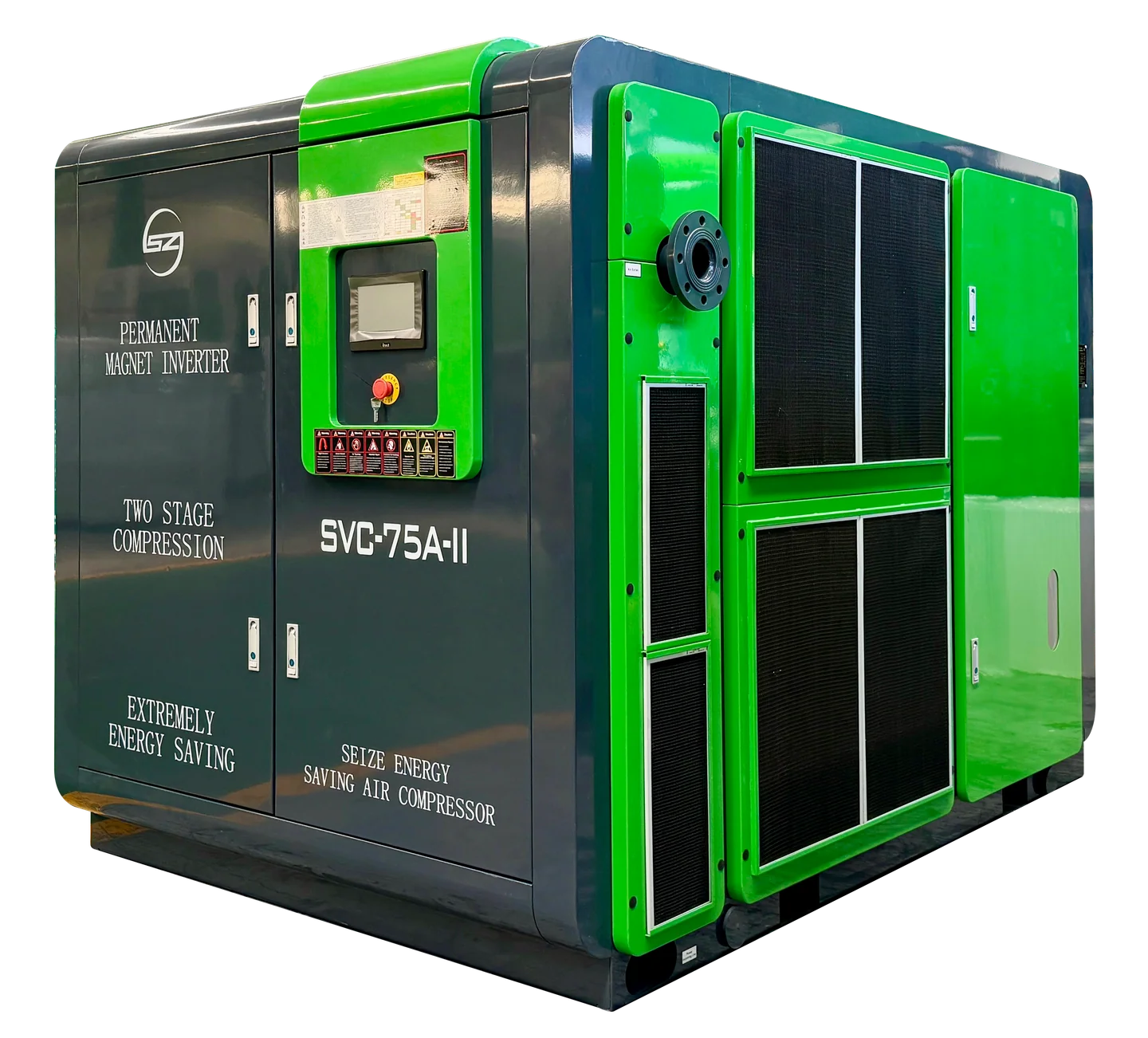
For a quotation, ask the supplier to explain the intended role of each machine. Review the permanent magnet variable-frequency compressor product page as part of the equipment discussion. The proposal should connect that role to measured demand and the required delivery condition. Include treatment and distribution in the discussion so the station is specified as a working system.
Review pressure increases as a documented change
Increasing station pressure can mask a downstream restriction while leaving the cause unresolved. Before making that change, establish why the affected process is short of pressure and whether a local correction is available.
The U.S. Department of Energy compressed air sourcebook recommends locating losses through measurements at different points. Its pressure-drop guidance also emphasizes selecting and maintaining treatment components and local connections for their required flow conditions.
If an operating adjustment is necessary, record its reason and review it against equipment limits and process requirements. Compare the resulting pressure behaviour and measured energy use. Avoid attaching a fixed savings claim to a change that has not been evaluated under the plant’s own conditions.
A practical compressed air pressure drop worksheet
Describe the complaint before collecting data
Prepare a short problem statement with the process owner. Name the machine, the affected operation and the reported consequence. Include whether the issue is new, intermittent or associated with a known change.
Ask operators what they observe first: a low-pressure alarm, slower movement, a failed cycle or an interruption elsewhere in the plant. Record those observations separately from suspected causes. The distinction helps the engineering team choose relevant measurement points.
- Machine or production area affected.
- Required inlet pressure and source of that requirement.
- Operating event and simultaneous users.
- Air quality requirement at the process.
- Recent equipment, maintenance or production changes.
- Available alarm and operating records.
This worksheet can accompany the maintenance request. It gives the measurement team a defined event to reproduce and an agreed process condition to restore.
Capture the observations in a consistent table
| Record field | Information to capture | Purpose |
|---|---|---|
| Location | Named test point on the diagram | Defines the section being compared |
| Time and operating state | Aligned timestamp and production activity | Connects the reading to the event |
| Pressure | Value, unit and instrument identification | Supports a comparable measurement |
| Station status | Running units, control states and alarms | Shows available supply behaviour |
| Component condition | Installed part and maintenance information | Supports a restriction investigation |
| Result | Observed production behaviour | Links pressure to process performance |
Keep raw records with the summary. A graph can show the timing clearly, but it should retain location labels and the production context. Unlabelled screenshots are difficult to use when the investigation passes to another engineer.
Rank corrective actions by evidence
List each proposed action beside the observation that supports it. A measured difference across a local component supports a different action from a plant-wide decline during simultaneous production. Include uncertainties and any additional measurement required.
Evaluate the expected effect, installation needs, maintenance implications and process acceptance requirements. The lowest purchase price does not establish the best correction if it leaves the same recurring disturbance or makes treatment harder to maintain.
Assign an owner to the action and to the follow-up measurement. The repair record should explain what changed and how the result was assessed. This makes the work useful for future expansion and prevents a temporary adjustment from becoming an unexplained permanent setting.
Prepare a supplier brief for compressed air pressure drop
Send evidence before asking for a machine size
A useful supplier brief contains the air-system diagram, affected process requirements and synchronized measurements. When considering an oil-injected permanent magnet compressor, include current compressor identification, treatment equipment and relevant operating records. Describe the demand event that causes the complaint.
Distinguish measured information from information still to be confirmed. If the flow profile has not been measured, say so. A supplier can then recommend the additional assessment needed instead of presenting an equipment size based on an uncertain assumption.
For a new facility, provide the available machine requirements and intended production sequence. Explain which equipment may operate together. Ask how the proposed station and distribution arrangement will support that sequence, including the required treatment and standby strategy.
Compare quotations on the same operating basis
Ask each supplier to identify the proposed delivery condition, applicable operating limits and the basis of the flow rating. Include air treatment in the scope and request information needed to assess its effect on available pressure.
Keep motor nameplate power, package input power and measured energy use separate in the comparison. They answer different questions. A product label or nominal motor rating cannot establish the electricity consumed by the complete installed system over a production cycle.
Require any claimed operating improvement to state its conditions and comparison basis. Where the proposal changes controls, piping or treatment as well as the compressor, the assessment should describe the combined scope. This makes the quotation review clearer and the eventual acceptance conditions easier to agree.
Connect the product choice to the actual application
SEIZE AIR’s local product materials cover oil-injected screw, oil-free screw, centrifugal and other compressor categories. Their applications and installation requirements differ. Product selection should therefore follow the process requirement and the measured system duty.
An oil-sensitive process needs a suitable complete air-quality arrangement. The water-lubricated oil-free screw compressor product page provides an equipment option to discuss with the supplier. A changing load requires review of equipment operating ranges and station control. A continuously operated system needs an agreed maintenance and availability plan. These requirements should appear in the quotation request.
When contacting SEIZE AIR for a system review, attach the problem statement and measurement worksheet. Use the industrial compressor supplier evaluation guide to structure the quotation review. Ask for model-specific information and a clear proposal scope. This allows the discussion to move from a general low-pressure complaint to a defined engineering decision.
Verify compressed air pressure drop corrections in production
Repeat the original event
Use the operating event from the original investigation as part of the acceptance check. Repeat the relevant production sequence with the same measurement locations where practical. Record any differences in demand or operating conditions that affect comparison.
Confirm whether the machine receives its required inlet condition throughout the event. Include recovery after a demand burst and operation with other relevant users. An improved idle reading is useful information, but it cannot establish production acceptance alone.
Keep the responsible process owner involved. A maintenance team may see a better pressure trace while an operator still experiences a failed cycle. The completed check should connect the measurements to the production outcome the correction was intended to achieve.
Review treatment and operating costs
Confirm that any treatment change continues to meet the process requirement. Record the verification method and responsible person. Sensitive applications may require checks beyond an ordinary maintenance inspection.
Where energy performance is part of the project, use measured package or station energy data and a clearly described production basis. Changes in output, operating hours and demand can affect the comparison. Explain those differences rather than converting a pressure improvement into an unsupported savings percentage.
The Australian Government compressed air equipment guide supports using operating data to understand demand and improvement opportunities. Apply that principle to the acceptance plan by keeping the production record alongside the energy record.
Keep a baseline for the next change
Save the updated drawing, component selections, controller settings and accepted pressure records in the plant’s maintenance system. Identify which configuration the baseline represents. A later machine addition should trigger a review of that configuration.
Assign a response to recurring symptoms. Operators should know which observations to record and whom to contact. Maintenance staff should have the approved replacement parts and the relevant equipment instructions available.
The value of the investigation extends beyond the repair. A documented baseline helps buyers assess expansion proposals, helps service teams recognize changing conditions and gives the process owner evidence that the air supply supports the intended operation.
Frequently asked questions about compressed air pressure drop
What causes compressed air pressure drop at a machine?
Possible contributors include restrictions through piping, filters, regulators, valves, hoses and couplings. A system-wide supply disturbance can also lower the pressure available to a machine. Compare synchronized upstream and downstream readings during the affected operating event to distinguish these patterns.
Does low pressure mean I need a bigger compressor?
A larger compressor may be relevant when measured demand exceeds available supply under the required conditions. A local restriction calls for a different correction. Establish the station’s behaviour and locate the loss before deciding whether additional generation capacity is necessary.
Can a variable-speed compressor fix every pressure dip?
Its suitability depends on the equipment’s operating range, demand pattern and station arrangement. It does not remove a restricted hose, filter or distribution branch. Assess control response and the downstream supply path together before choosing the correction.
Should I remove a filter to reduce the loss?
Maintain the air quality required by the process. Inspect and select filtration using the supplier’s instructions and relevant operating conditions. If a filter is implicated, investigate its condition and suitability rather than treating permanent removal as the acceptance solution.
How much pressure loss is acceptable?
The process must receive its required inlet pressure under the specified operating conditions. Establish a system pressure budget with the responsible engineer and component suppliers. General guidance can inform design, but acceptance should reflect the particular process, equipment and measured demand.
Will adding a receiver solve the problem?
Storage can be considered for a defined intermittent demand event. Its usefulness depends on location, available pressure, recharge conditions and the restriction being investigated. Ask the system engineer to assess those factors before specifying a receiver or assuming it will correct inadequate continuous supply.
Turn the pressure complaint into a clear decision
A useful compressed air pressure drop investigation connects the machine requirement, a mapped supply path and synchronized production measurements. It explains where pressure changes, what operating event triggers the problem and which corrective action the evidence supports.
Start with the affected process and retain its air quality requirement. Review local connections, treatment, distribution and station behaviour in a logical order. After the change, repeat the event and keep the accepted baseline.
Send SEIZE AIR your air-system diagram and pressure records to discuss the next assessment or a model-specific quotation. Include your production sequence and process requirements so the proposal addresses the complete supply duty.