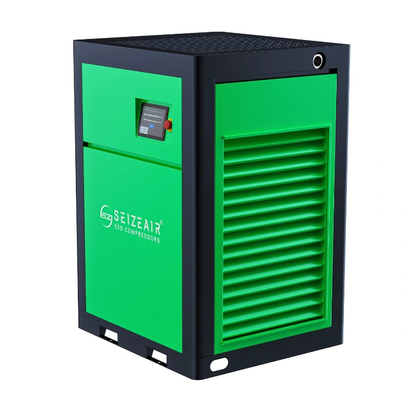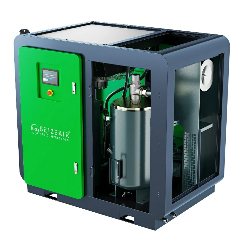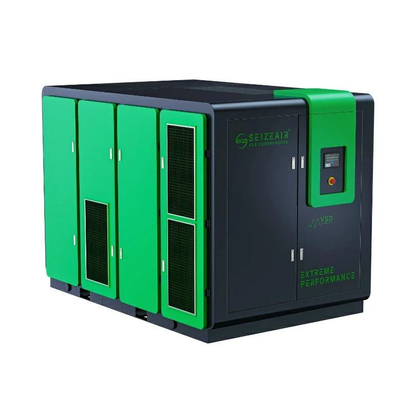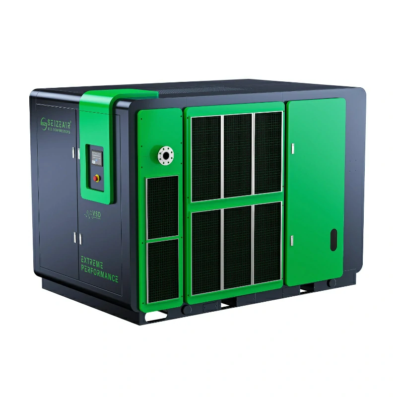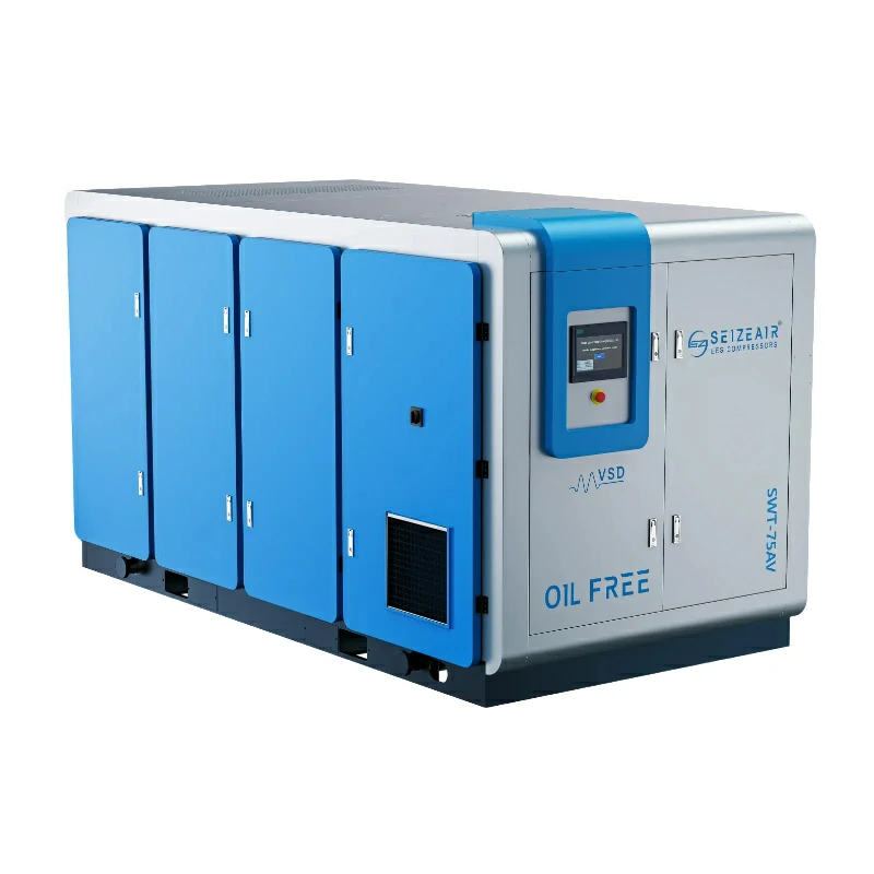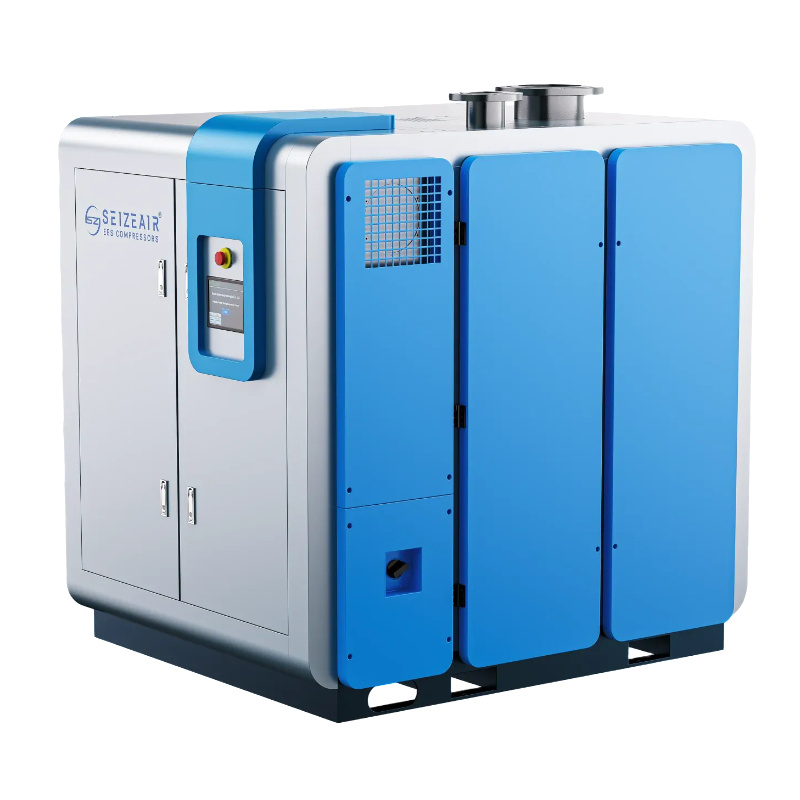


An air compressor for pet blowing — that is, for PET (polyethylene terephthalate) bottle stretch-blow molding — is specified by pressure, flow and air purity in a way that general shop air never is. A blow molder inflates a heated preform against a mould with a short, sharp pulse of high-pressure air, and it does so several times a second per cavity. The compressor and its treatment train must deliver that pulse at a stable pressure, without oil, water or particles that would show up as defects in a food or beverage bottle. This guide explains how the two pressure circuits work, why oil-free Class 0 air and low dew points are non-negotiable, which compressor technologies suit each stage, and how to size a system from real machine data. It includes a fill-in sizing worksheet, a bottle-defect-to-air-cause table, commissioning and maintenance checklists, and a practical FAQ for a real enquiry.
What an air compressor for PET bottle blowing must actually deliver
Stretch-blow molding turns an injection-moulded preform into a finished bottle in three steps: the preform is heated, a stretch rod extends it, and compressed air inflates it against the mould cavity. Air is used at more than one pressure. A low-pressure pre-blow starts the expansion gently so the material distributes evenly; a high-pressure final blow completes the shape and sets the wall thickness and base. Many machines also use compressed air for stretch-rod actuation, mould clamping and general machine functions. Treating all of these as one demand is the most common cause of an undersized or inefficient installation.
Published guidance from packaging and compressor sources typically places pre-blow in a range of roughly 6 to 15 bar and final blow in a range of roughly 25 to 40 bar, depending on bottle size, shape and resin. For non-commercial background on the equipment side of the process, packaging machinery industry association publishes background on converting and filling lines. These are indicative ranges, not a specification for your line. The blow molder manufacturer’s own documentation is the only acceptable source for the pressures and consumption figures you design to.
Why the pressure pulse matters more than the average
A rotary blow molder is a pulsed load. Each cavity draws a short, high-volume breath, and the breaths from multiple cavities overlap in a repeating pattern. The average flow over an hour can look modest while the instantaneous demand is severe. If the receiver and distribution cannot buffer that pulse, pressure at the blow valve sags during each event, and the bottle wall thickness varies from cycle to cycle. This is why receiver sizing and the location of pressure measurement deserve as much attention as the compressor itself.
Two pressure circuits, not one
A well-designed PET blowing installation separates the low-pressure pre-blow and machine air from the high-pressure final blow. Generating all the air at 35 or 40 bar and then throttling most of it down to 10 bar for pre-blow and actuation wastes the energy invested in the extra compression. Two circuits, each at the pressure its task needs, are more efficient and give finer control over the blowing profile. The high-pressure circuit usually includes a booster or a two-stage machine; the low-pressure circuit is served by a standard oil-free screw compressor in the 7 to 13 bar class.
High-pressure final blow circuit
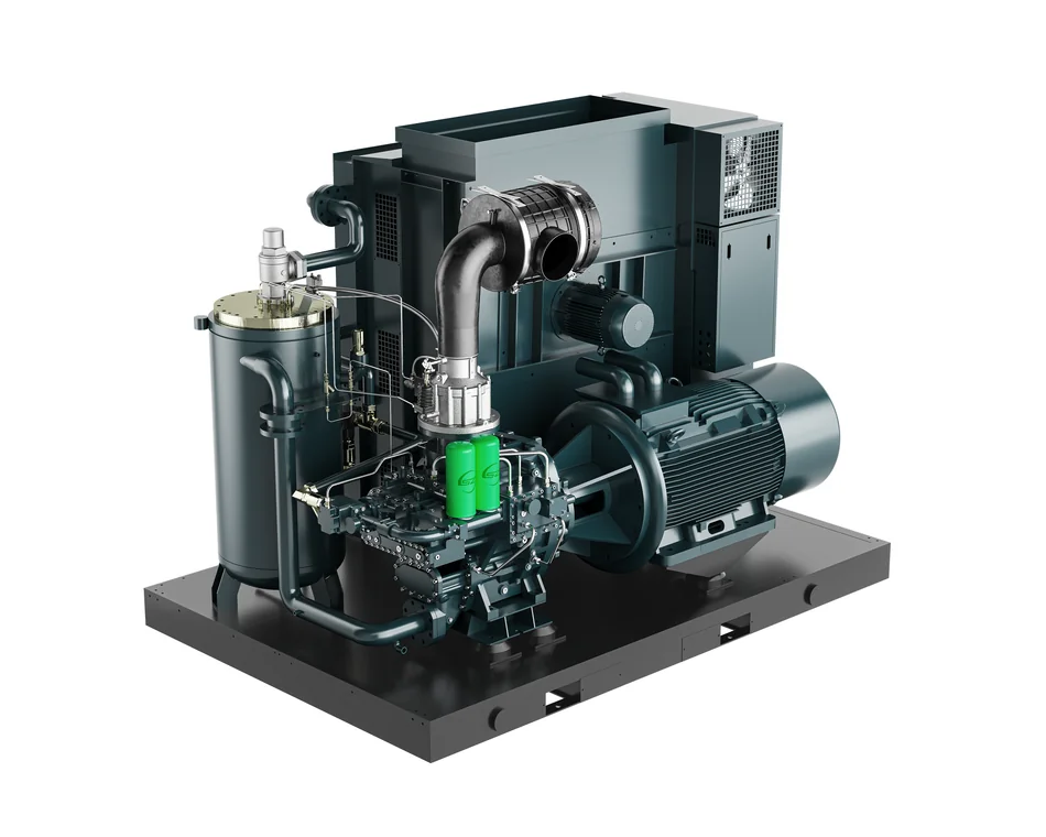
The final blow circuit is the demanding one. It has to reach the machine’s required inlet pressure, hold it through simultaneous cavity pulses, and supply it oil-free and dry. Where the blow molder needs 30 to 40 bar, this normally means a two-stage oil-free screw compressor, a water-injected two-stage machine, or a lower-pressure oil-free compressor feeding an oil-free piston booster that raises the air to the final pressure. The right choice depends on total flow, the number of machines, and how much redundancy the plant needs. Our oil-free screw compressor range is the starting point for the base air stage.
Low-pressure pre-blow and machine air circuit
Pre-blow air touches the heated preform, so it must be just as clean as the final blow air even though it is at a much lower pressure. An oil-injected machine is not acceptable here, because oil in the pre-blow stage can create visible defects and a food-contact risk. A standard oil-free rotary screw compressor in the 7 to 13 bar class is the usual answer, serving pre-blow, stretch-rod actuation, clamping and other machine functions. Keeping this circuit independent also means a fault in the high-pressure package does not stop the whole line.
Why oil-free Class 0 air is non-negotiable in PET blowing
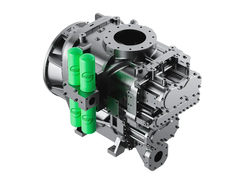
The compressed air in a PET blowing process comes into direct contact with the inside of a container that will hold food or drink. Oil aerosol carried into the bottle can appear as specks, cause taste or odour complaints, and breach the hygiene expectations that food and beverage producers operate under. Regulators treat materials that contact food with particular care; the United States federal food-contact regulations are one example of the framework producers must respect. A compressor supplier cannot certify the whole bottle line, but the air it supplies must not be the weak link.
Reading the ISO 8573-1 purity classes
Air purity is described by the ISO 8573-1 framework, which separates oil, solid particles and water into classes. Class 0 for oil is the designation buyers look for in food, beverage and pharmaceutical air, and it means no oil is introduced by the compression process itself. Particle and water classes are specified separately, so a supplier who quotes only “oil-free” has not given a complete purity specification. Ask for the target class for each contaminant, the point at which it applies, and how it will be verified after installation. Our purity standards guide explains how these classes are read.
Oil-free does not mean treatment-free
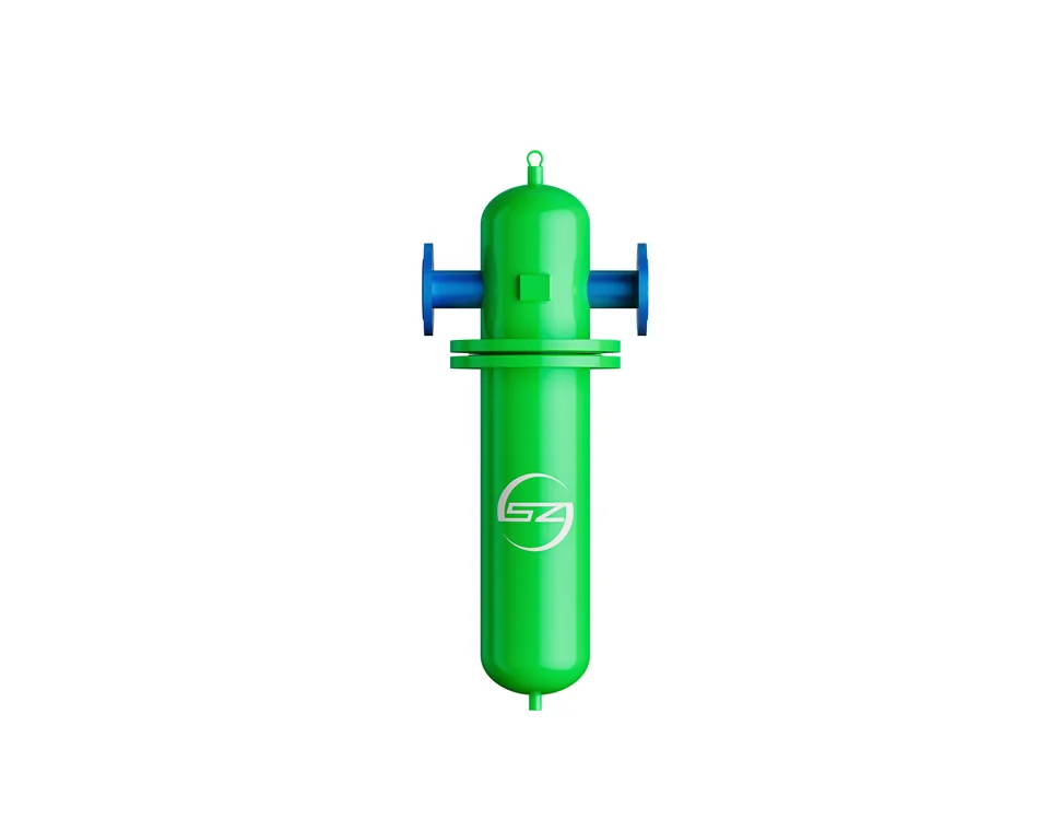
Even with an oil-free compressor, the air still needs drying and filtration. Water vapour from the room condenses as the air cools, and particles can enter through the intake or be shed by pipework and filter elements. A typical treatment train includes a water separator, a coalescing filter for any trace ambient hydrocarbon, a particulate filter, a dryer sized for the flow and inlet temperature, and a high-quality point-of-use filter at the blow molder. Class 0 removes the oil source; it does not remove the need to control everything else. Our Class 0 water-injected versus dry comparison sets out the two oil-free technologies and their different treatment needs.
Moisture, dew point and bottle quality
Water is the quiet enemy of PET blowing. Moisture in the air can produce visible water marks on the preform or bottle, interfere with even heating in the oven, and support microbial growth in receivers and pipework. Because the air expands rapidly at the blow valve, local cooling can drive condensation even when the bulk air line looks dry. The normal design response is to set a pressure dew point below the lowest temperature the air will see, including the expansion at the point of use.
Choosing between refrigerated and desiccant drying
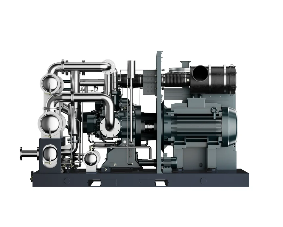
A refrigerated dryer is often sufficient for general plant air, but the low dew points associated with high-quality PET blowing frequently call for a desiccant dryer, especially where lines run through cool areas or where the product is sensitive. Water-injected oil-free compressors deliver saturated air and place a higher load on the dryer, which must be accounted for in sizing. The correct dew point is a specification for your line, not a number to copy from an article; our air dryer selection guide covers how dryer type and operating conditions interact. Whichever dryer is chosen, drains and low points must be designed in from the start.
Drains, condensate and where water collects
Dryers do not remove water from a system; they move it to a place where it can be drained. Every separator, receiver and low point in the distribution needs a drain that is accessible, correctly sized and included in the maintenance plan. A failed automatic drain can quietly refill a receiver and send a slug of water toward the blow molder during a peak demand event, producing a batch of defective bottles before anyone suspects the air system. Where a line passes through a cool area, insulation or trace heating may be appropriate, but the design should first eliminate unnecessary low points and dead legs.
Condensate from a compressed air system is not clean water. It can carry oil traces from ambient intake, dust and treatment chemicals, and it should be handled according to local environmental rules rather than discharged into a storm drain. In a beverage plant, hygiene expectations extend to the utility rooms, so drained points should be kept tidy and free of standing water. Record the condition of each drain during the weekly round; a slow drain is an early warning that a filter or separator is doing more work than intended, and catching it early is far cheaper than investigating a quality complaint on the line.
Pressure drop and why setpoints need margin
Every metre of pipe, every elbow, filter and dryer costs pressure. A long distribution run can consume several bar between the compressor outlet and the blow valve, so setting the compressor exactly at the mould’s minimum requirement guarantees under-pressure at the machine. Add a deliberate margin to the setpoint and verify it with a gauge at the point of use during production, not at the compressor. Our pressure drop troubleshooting guide describes how to measure where the loss occurs. Oversizing pipework and keeping runs short is cheaper than paying to compress air that is then wasted across a restriction.
Compressor technologies for PET blowing
Three technology families dominate this application: oil-free screw compressors, water-injected oil-free screw compressors, and oil-free piston boosters, often combined into a single package. Each reaches high pressure by a different route and brings different installation and maintenance consequences. The choice is rarely about which technology is universally best; it is about which fits the required flow, pressure, air quality and site conditions.
Two-stage and three-stage oil-free screw
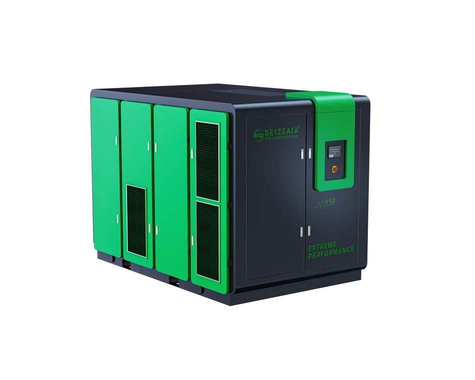
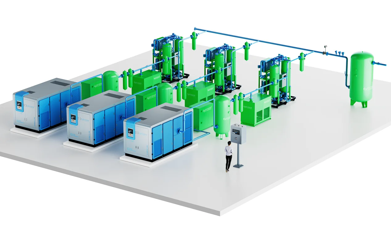
A multi-stage dry oil-free screw compressor compresses air progressively through separate airends, with intercooling between stages, to reach the final pressure without oil in the compression chamber. It delivers a continuous flow with no pulsation, which suits a line with many cavities cycling rapidly. SEIZE AIR’s oil-free screw and three-stage offerings are documented in the product literature and on the product pages; verify the exact model table and its stated reference conditions before comparing capacities. Higher stage count generally means higher outlet pressure capability, but confirm the configuration for your required flow.
Water-injected oil-free screw
Water-injected single-screw machines use water as the compression fluid, achieving oil-free air and near-isothermal compression that can be efficient at high pressure in a single stage. The trade-offs are real: the discharged air is saturated, so the dryer must work harder; water quality and treatment become part of the maintenance regime; and freezing must be considered in cold environments. Our water-lubricated oil-free range illustrates the technology. It can be a strong choice where water treatment is already managed competently on site.
Oil-free piston boosters and tandem packages
For the highest final pressures, a common arrangement pairs an oil-free screw compressor, which supplies base air efficiently, with an oil-free piston booster that raises the pressure for final blow only. Piston boosters tolerate high pressure ratios and are well proven in PET service, but they introduce pulsation that must be damped and wear parts that need regular attention; filtration downstream catches ring debris. Integrated screw-plus-booster packages combine both stages on one skid with controls and treatment. The oil-free compressor category is the place to start a model search once your duty point is known.
Sizing worksheet: start from the blow molder’s own data
No generic example can size a blowing air system reliably, because consumption depends on cavity count, bottle volume, cycle rate, blow pressure and whether air recovery is fitted. Use the worksheet below with the actual documentation from your blow molder and measurements from your site. Every blank has a source column so the figure can be traced to a document or a reading. Where the machine quotes consumption in litres per cycle or normal cubic metres, keep the unit until the final conversion so reference conditions are not silently mixed.
| Input | Value | Unit | Source to check |
|---|---|---|---|
| Final blow pressure at the machine inlet | ________ | bar | Blow molder manual for the bottle format |
| Pre-blow pressure at the machine inlet | ________ | bar | Blow molder manual |
| Air per bottle, final blow | ________ | Nl or Nm³ | Blow molder consumption table |
| Air per bottle, pre-blow and actuation | ________ | Nl or Nm³ | Blow molder consumption table |
| Cavities and cycles per hour | ________ | count / h | Machine specification and production plan |
| Simultaneous blow events at peak | ________ | count | Observation on a running machine |
| Installed pressure loss to the blow valve | ________ | bar | Gauge difference measured while blowing |
| Target pressure dew point and location | ________ | °C | Product quality specification and coldest line point |
| Target ISO 8573-1 classes (oil / particle / water) | ________ | class | Food-contact and product quality requirements |
| Compressor free air delivery at working pressure | ________ | m³/min | Current catalogue table with reference conditions |
| Receiver volume and relief setting | ________ | litres / bar | Vessel documentation and local rules |
Complete the worksheet, convert all flows to one consistent reference basis, and compare the peak simultaneous demand with the free air delivery at your working pressure and site conditions. Then check that the machine inlet pressure plus measured distribution loss is comfortably below the compressor setpoint. Only when both checks pass should the dryer, filters and receiver be finalised. Re-run the worksheet for every new bottle format or line speed change; the calculation is cheap, and a retrofit after a line is commissioned is not. For background on how machine-side demand is framed, general packaging machinery industry sources offer context, but the blow molder data sheet remains authoritative.
Receivers, pulsation and system stability
The receiver is not optional storage; it is part of the process. A blow molder draws air in pulses, and the receiver buffers those pulses so the compressor sees a smoother average load and the machine sees a steadier pressure. Size it from the actual blow volume and the number of simultaneous events, not from a rule of thumb. Place it close to the point of use where practical, fit the correct relief valve and isolation, and arrange a drain at the lowest point so condensation cannot collect.
High-pressure receivers need particular care. They should be selected and installed to the applicable pressure-vessel rules for the site, with documented inspection intervals and a clear maintenance responsibility. Where a line runs several machines, a shared high-pressure header with adequate buffer volume can improve redundancy, but it must be sized so one machine’s peak does not starve another. Separate headers for pre-blow and final blow avoid the common mistake of throttling high-pressure air down for low-pressure tasks.
Configuration options: central, zoned or machine-mounted
There is no single layout that suits every plant. A small operation with one blow molder may be best served by a compact package dedicated to that machine. A large beverage plant with several lines often uses a central high-pressure station with a ring main and generous buffering, which improves utilisation and maintenance access. Between the two, a zoned arrangement serves a group of machines from a local skid. Decide from the measured duty cycle, the distance between machines and the cost of downtime.
When a dedicated high-pressure package wins
A dedicated package is easy to match to one machine’s consumption profile, simple to commission, and keeps a fault localised. It also makes it straightforward to tune the pressure to a single bottle format. The cost is duplicated equipment if several machines are added later, and the plant loses the efficiency that comes from sharing a well-loaded central unit. Choose this route where production is small, formats differ markedly between machines, or the lines are physically far apart.
When a central high-pressure station wins
A central station can run larger, more efficient machines at a favourable part-load point and serve several blow molders through a regulated ring main. Maintenance is concentrated, spares are shared, and capacity can be added with a parallel unit. The design must account for distribution losses and for the simultaneous peak of all connected machines, and it needs enough buffer volume to isolate one machine’s pulse from another. Where reliability is critical, N+1 capacity on the high-pressure circuit is often cheaper than the lost production of a stopped line.
Energy and part-load behaviour
Compressed air is an energy-intensive utility, and PET blowing is a high-pressure application, so inefficiency is expensive. The largest single saving usually comes from not over-compressing: generate pre-blow and machine air at low pressure instead of throttling high-pressure air down. The next is matching compressor output to the demand profile. Where demand fluctuates across shifts or bottle formats, variable-speed control on the low-pressure machine reduces unloaded running; on the high-pressure side, staging multiple units so that only the required number runs can achieve a similar effect.
Heat of compression is another recoverable resource where a plant has a steady demand for hot water, although the economics depend on the site and are outside the scope of a general guide. When comparing machines, ask for specific power at your actual working pressure and reference conditions, and model a realistic production profile rather than full-load figures. Our oil-injected versus oil-free comparison discusses the broader trade-offs, but in food-contact PET service the oil-free requirement normally decides the technology before efficiency is optimised. Our working pressure guide explains why setpoints should be based on the point of use.
Installation and commissioning checklist
A correct specification can be spoiled by a hurried installation. Work through the following as verification questions and tick an item only when someone has observed the result. Keep the signed record with the plant documentation; the baseline readings become the reference for every later fault investigation, particularly for a pulsed high-pressure system where small changes have large effects.
- Confirm the delivered model, serial number and that the oil-free claim matches the certificate scope.
- Verify free air delivery and pressure at simultaneous peak demand with a gauge at the blow valve.
- Confirm pre-blow and final-blow headers are separate and regulated independently.
- Measure pressure drop across the treatment train and distribution at production flow.
- Check pressure dew point at the point of use and confirm all drains discharge correctly.
- Verify ISO 8573-1 class targets, filter grades, orientation and recorded initial pressure drop.
- Inspect the intake for contamination and confirm ventilation and cooling are adequate.
- Test relief valves, isolators, automatic shutdowns and emergency stops on both circuits.
- Check receiver documentation, inspection status and relief setting for the high-pressure vessel.
- Record a baseline of bottle weight, wall distribution and visible quality at commissioning.
Bottle defects and air-side causes
When bottle quality drifts, start at the air supply before adjusting the mould or the oven. Many visible defects have an air-side explanation, and the table maps what operators see to the check most likely to confirm it. Work from the blow valve back toward the compressor, changing one variable at a time and recording the result. If two symptoms appear together, treat them as two faults until a shared cause is proven.
| Observed symptom | Likely air-side cause | Check to confirm |
|---|---|---|
| Uneven wall thickness, cycle to cycle | Pressure sag during the blow pulse, small receiver | Gauge trace at blow valve, receiver volume, simultaneous events |
| Specks or spots inside the bottle | Particles or oil carry-over in the air stream | Point-of-use filter, purity class, upstream contamination audit |
| Water marks or hazy areas | Condensation from high dew point air | Dew point at point of use, drains, cold line sections |
| Bottle not fully formed | Insufficient final blow pressure or flow | Machine inlet gauge under load, compressor delivery, distribution loss |
| Preform bursts during pre-blow | Pre-blow pressure too high or badly profiled | Pre-blow regulator and timing against machine documentation |
| Pressure falls over the shift | Dryer icing, blocked filter or rising inlet temperature | Filter differential pressure, dryer status, ambient conditions |
| Odour or taste complaint | Ambient hydrocarbon or oil contamination at intake | Intake location, carbon filtration, oil-free certificate scope |
Maintenance and hygiene schedule
A PET line often runs long hours, and air quality is only as good as the maintenance of the treatment train. Set intervals from observed conditions rather than a generic calendar, and keep a log with date, readings and the person responsible. Product-contact air demands discipline: a filter that is past its service life or a drain that has failed can undo an otherwise excellent specification in a single shift.
| Frequency | Task | Why it matters in PET blowing |
|---|---|---|
| Daily / per shift | Check drains, dew point reading and point-of-use filter condition | Protects bottle appearance and food-contact hygiene |
| Weekly | Inspect intake filter, record pressure drop, check for leaks | Early warning before purity or pressure drifts |
| Monthly | Verify gauges at blow valve, check dryer and drain operation | Catches loss of setpoint before bottle quality suffers |
| Per service interval | Replace filter elements, service booster wear parts per manual | Sustains the purity claim and high-pressure reliability |
| Annually | Review vessel inspection, re-run sizing for new formats | Keeps the system matched to production and compliant |
Total cost of ownership
The purchase price of an air compressor for PET blowing is only a fraction of what it will cost over its life. Energy dominates for a machine running at high pressure for long hours, followed by maintenance, filter elements, dryer operation and the cost of lost production. A dual-pressure design, correctly sized receiver and well-matched booster often save more than a discount on the machine. Compare suppliers on specific power at your working pressure, service intervals, consumable prices and the availability of local support.
Reliability has a direct production value. A single blow molder on a filling line can stop an entire bottling shift, so redundancy on the high-pressure circuit and access to spare parts are worth pricing explicitly. A vendor who can document the oil-free certificate scope, the purity classes, the dryer performance at your conditions and a realistic maintenance plan is more useful than one who quotes only a nominal pressure. Our overview of oil-free compressor benefits gives additional background for the discussion, and our engineering team can turn a completed worksheet into a shortlist based on real equipment.
Frequently asked questions
What pressure does a PET bottle blowing compressor need?
Industry guidance commonly cites roughly 6 to 15 bar for pre-blow and roughly 25 to 40 bar for final blow, but the correct values come from your blow molder’s documentation for the specific bottle format. The compressor setpoint must also include margin for distribution pressure loss and the pulse at each blow event.
Can an oil-injected compressor be used if filters are fitted?
For food and beverage PET bottles, oil-free air is the expected starting point. Downstream filtration cannot reliably deliver Class 0 from an oil-injected machine, and it adds pressure drop and a continuing dependency on element changes. Oil-free compression removes the oil at the source. Confirm the certificate scope for the exact models supplied.
Do I need two compressors for pre-blow and final blow?
Not always, but two circuits are usually more efficient. Generating all air at 40 bar and throttling most of it to 10 bar wastes the extra compression. A low-pressure oil-free screw for pre-blow and machine air, plus a high-pressure stage or booster for final blow, is a common and economical arrangement. The worksheet will show whether your demand justifies it.
Why is my bottle wall thickness varying?
Pressure sag during the blow pulse is a frequent cause. Check the gauge at the blow valve during production, the receiver volume and the number of simultaneous blow events. Also confirm the pre-blow profile, because uneven pre-blow distribution cannot be corrected later in the final blow.
How dry does the air need to be?
The target is a specification for your line, not a universal number. It should be below the lowest temperature the air will see, including expansion at the blow valve, and it should satisfy your product quality requirements. Water-injected compressors and cool line sections both raise the dryer duty, so size the dryer from real inlet conditions.
Final checklist before you order
Bring the completed worksheet to the conversation and ask for documents rather than adjectives. Request the free air delivery table at your working pressure and reference conditions, the exact models covered by the oil-free certificate, the stated pressure dew point and purity classes at your site conditions, and the receiver and relief arrangements for the high-pressure vessel. Ask for service intervals, consumable prices and local support in writing. A supplier who answers these plainly is far more useful than one who quotes a single pressure figure and promises clean air.
Summarise the decision on one page: measured demand for each circuit, chosen compressor and booster arrangement, treatment train, receiver and distribution, pressure and purity targets, and who owns each maintenance task. An air compressor for PET blowing succeeds when the whole system is specified around the realities of the blow molder — the pulse, the pressure, the hygiene requirement and the production schedule. Measure the demand, insist on oil-free and dry air, verify the installed result, and the compressed air system will support bottle quality instead of limiting it.