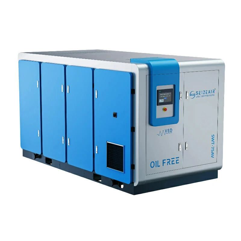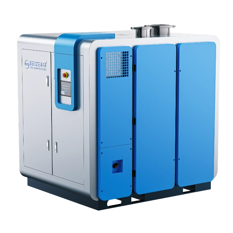


Air compressor for spray painting selection is an air-quality and system-design problem, not a horsepower contest. A paint booth needs compressed air that arrives at the gun at a steady pressure, in the volume the gun actually consumes, and free of the water, oil and particles that show up as visible defects in the finished coat. This guide walks through how to build a demand profile from real spray gun data, choose an air purity class, pick a compressor and control strategy, specify drying and filtration, size the receiver and pipework, address booth safety, and verify the whole system at commissioning. It also includes a defect-to-root-cause table, a maintenance schedule and a supplier question list you can use on a real enquiry.
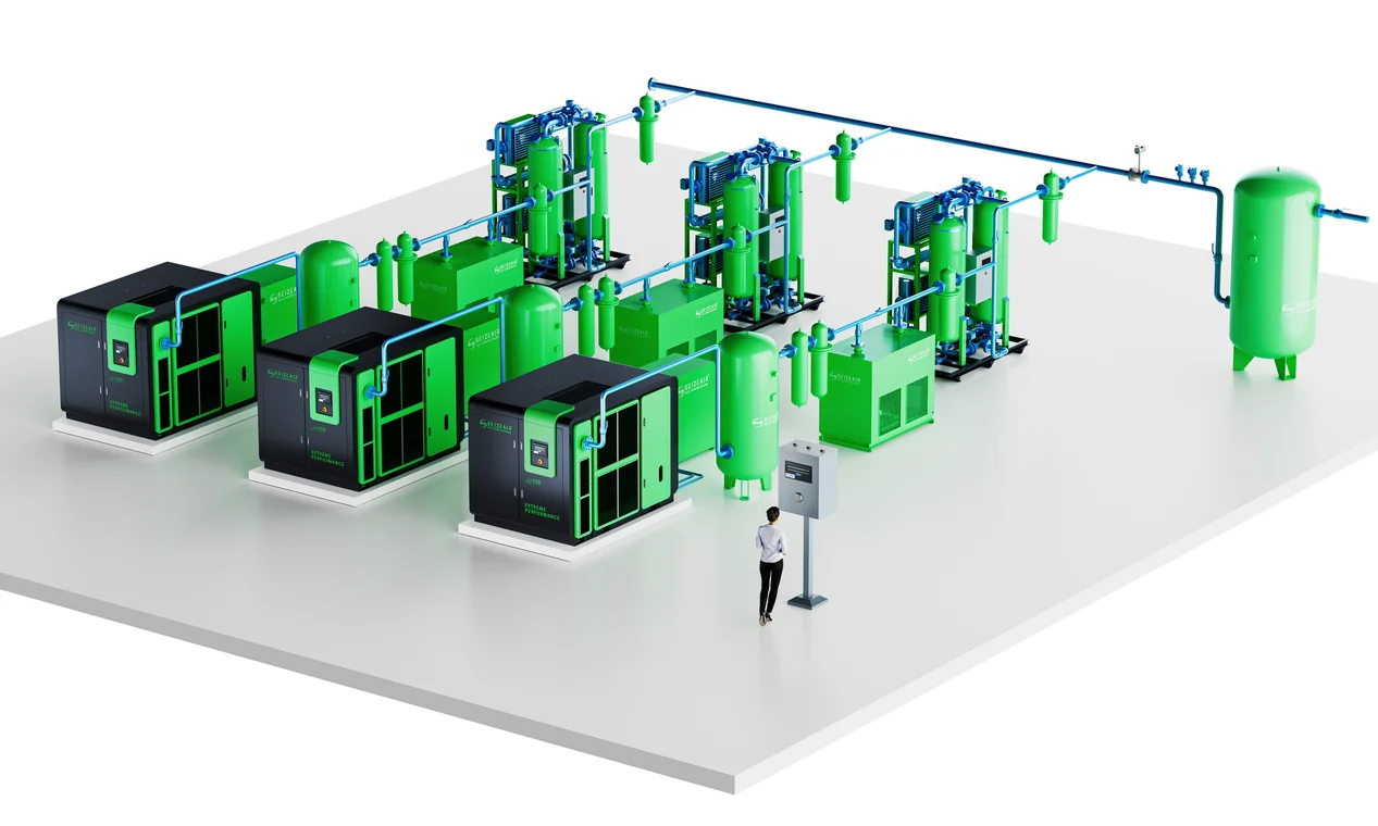
What an air compressor for spray painting must actually deliver
Three requirements decide whether a finishing line produces saleable parts or rework. First, the system has to deliver enough free air at the gun inlet while the trigger is open. Second, the pressure at that inlet must stay inside the window the gun and the coating manufacturer specify. Third, the air has to be clean and dry enough that it does not contaminate the film. Any one of the three can fail while the other two look perfectly healthy, which is why a compressor that seems correctly sized on paper can still produce fisheyes, blushing or orange peel on the panel.
Buyers often start by asking for a kilowatt rating or a tank size. Both are consequences of the real specification, not the specification itself. A useful enquiry begins with the number of guns, each gun’s air consumption at its stated inlet pressure, how many operators spray at the same moment, the duty cycle of the booth, the purity class the coating requires, and the length and diameter of the distribution line. Everything else, from the airend to the last filter bowl, follows from those inputs.
Air quality is a process variable, not a bonus feature
In most pneumatic applications, a little moisture or oil aerosol is an inconvenience. In coating, it is a defect generator that travels through the same hose as the paint. Water condensing at the gun can change atomisation and leave a milky cast in the film. Oil aerosol can collapse surface tension locally and create craters. Solid particles become nibs that have to be sanded and polished out. Treating air treatment as an optional accessory is therefore the single most expensive shortcut in a booth project, because the cost shows up later as labour and scrap rather than as a line item on a quote.
Associations such as the Compressed Air and Gas Institute publish guidance on how compressed air purity is specified and tested, and those definitions give a common language for discussing requirements with a supplier. Ask for the target purity class in writing, then ask how the proposed treatment train will be validated after installation. A verbal assurance that the air is “clean” is not a specification and cannot be audited.
Flow, pressure and duty cycle are separate specifications
Free air delivery describes volume, usually in cubic metres per minute, litres per second or cubic feet per minute, measured at declared reference conditions. Working pressure describes the force available at a point in the system. Duty cycle describes how long and how often the demand occurs. A small booth with one intermittent gun, a furniture line with two continuous guns and a refinish shop that also runs sanders and lifts place very different demands on the same nominal pressure. Conflating the three leads to the classic failure of buying a machine with adequate pressure but inadequate continuous flow.
Catalogue flow figures also need their reference conditions read carefully. Some SEIZE AIR catalogues state free air delivery at 1 bar and 20 °C under ISO 1217 Annex C, and other documents quote different inlet conditions. Ask which standard and which inlet conditions apply to the figure you are comparing, and confirm altitude and ambient temperature for the installation site. Our guide to working pressure selection explains why a pressure number without a location in the system is almost meaningless.
How contaminated compressed air creates paint defects
Most finish complaints are diagnosed at the gun, the coating or the technique. A disciplined audit starts one step earlier, at the air line. The three contaminant families leave recognisable signatures, and matching the signature to the contaminant shortens the troubleshooting loop considerably. Keep a simple log of when defects appear, which booth was running, and what the dryer and drains were doing at the time; patterns usually emerge within a few shifts.
Water: blushing, spotting and adhesion loss
Compression concentrates the water vapour already present in the intake air. As the air cools in the receiver and the distribution line, that vapour condenses. The risk rises when the booth is far from the dryer, when lines run through cold spaces, or when a dryer is bypassed during maintenance. Liquid water reaching the gun can produce a cloudy or whitened film, uneven atomisation, spatters and, over time, corrosion inside the tool. A pressure dew point target set below the lowest temperature the line will see is the normal design response; the specific value belongs in the coating and equipment documentation, not in a generic article.
Condensate management is as important as the dryer itself. A dryer can perform correctly while a failed automatic drain floods the receiver, or while a low point in the pipework collects water that is then pushed toward the booth during a peak demand event. Our air dryer comparison and selection guide covers how dryer type, dew point and drain arrangements interact, and why the lowest point of every branch needs a planned outlet.
Oil: fisheyes, craters and intercoat problems
Oil can enter the air stream as aerosol from a lubricated airend, as vapour, or as residue picked up from an old, poorly maintained distribution line. On a prepared surface it creates small circular depressions where the coating cannot wet out. The same contamination can compromise adhesion between coats, which may only become visible after masking is removed or after the part has been in service. Retrofitting filters downstream of an oil-injected compressor can control this, but it adds maintenance items, pressure drop and a dependency on replacement elements being changed on time.
The alternative is to eliminate oil from the compression chamber. Our comparison of oil-injected and oil-free compressors sets out the trade-offs in capital cost, maintenance and risk. For a finishing line, the decision should be driven by the coating specification and the cost of a rejected panel, not only by the purchase price of the machine.
Particles: dirt nibs, roughness and rework
Rust scale from steel pipe, desiccant dust from a dryer, intake dust and worn seal fragments all arrive at the gun as particles. Point-of-use filtration is the last barrier, and it should be sized for the actual flow with a clean pressure drop that the system can afford. A filter that is too small becomes a restriction; a filter that is never changed becomes a contamination source. Record the initial differential pressure at commissioning so that later readings have a baseline. Where a booth has been in service for years, inspect a section of pipe internally before blaming the compressor for a sudden run of nibs.
Step 1: Build the demand profile from real spray gun data
Start with the manufacturer’s data sheet for each gun, not with a rule of thumb. The sheet gives air consumption at a stated inlet pressure for a given nozzle and cap combination. Different atomisation technologies and different nozzle sets consume noticeably different amounts, and a change of cap can invalidate an earlier calculation. Copy the value, the pressure at which it applies, and the units into one worksheet. If a sheet quotes consumption in cubic feet per minute at a gauge pressure, keep those units until the final conversion to avoid silently mixing gauge and absolute references.
Read the gun rating at the point where it applies
Inlet pressure at the gun is not the same as pressure at the compressor outlet. Regulators, filters, hose length, quick couplers and fittings all consume a share of the available pressure. Design the generation pressure from the sum of the gun requirement and the expected losses, then verify it with a gauge at the gun during a live spray test. Where several guns share a header, the loss calculation has to use the simultaneous peak flow, not the average. Our plant pressure drop troubleshooting guide describes the measurement method and the usual places where an otherwise healthy system loses pressure.
Add simultaneous demand, then check the peak events
Multiply each gun’s consumption by the number of guns that can be triggered together, then add other pneumatic users that can coincide: booth air motors, powder or paint pumps, pneumatic lifts, blow-off stations and cleaning tools. A diversity factor is legitimate only when it reflects how the shift is actually run and when operators cannot physically overlap. Verify it on the floor with the production supervisor. Blow-off guns are frequent hidden loads because they are cheap to install, unrestricted, and often left open. Where blow-off is necessary, fit a regulated, restricted nozzle and document its consumption in the same worksheet.
Leave headroom for growth, fouling and hot weather
A system designed to run at exactly the calculated peak has no reserve for a partly loaded filter, a hotter intake, a second operator or a future booth. At the same time, generous oversizing without speed control creates short cycling and poor part-load efficiency. This is the point where the shape of the demand curve matters as much as its maximum. A booth with one gun used intermittently needs a different control strategy from a line where two guns run continuously for hours, even if both produce similar daily air volumes. Record the expected pattern in the enquiry so the supplier can propose a control scheme rather than just a larger motor.
Step 2: Specify the air purity class before choosing the machine
ISO 8573-1 defines purity classes for solid particles, water and oil in compressed air, and it is the usual framework for writing a booth requirement into a specification. Class 0 is not simply a stricter numbered class; it is a user- or manufacturer-specified requirement that must be stated with its limits and supported by test evidence. Ask the coating supplier which class or which explicit limits apply to the product being sprayed. Then translate that answer into a treatment train and a test plan. The certificate held by a compressor covers the machine, not the whole distribution system downstream of it.
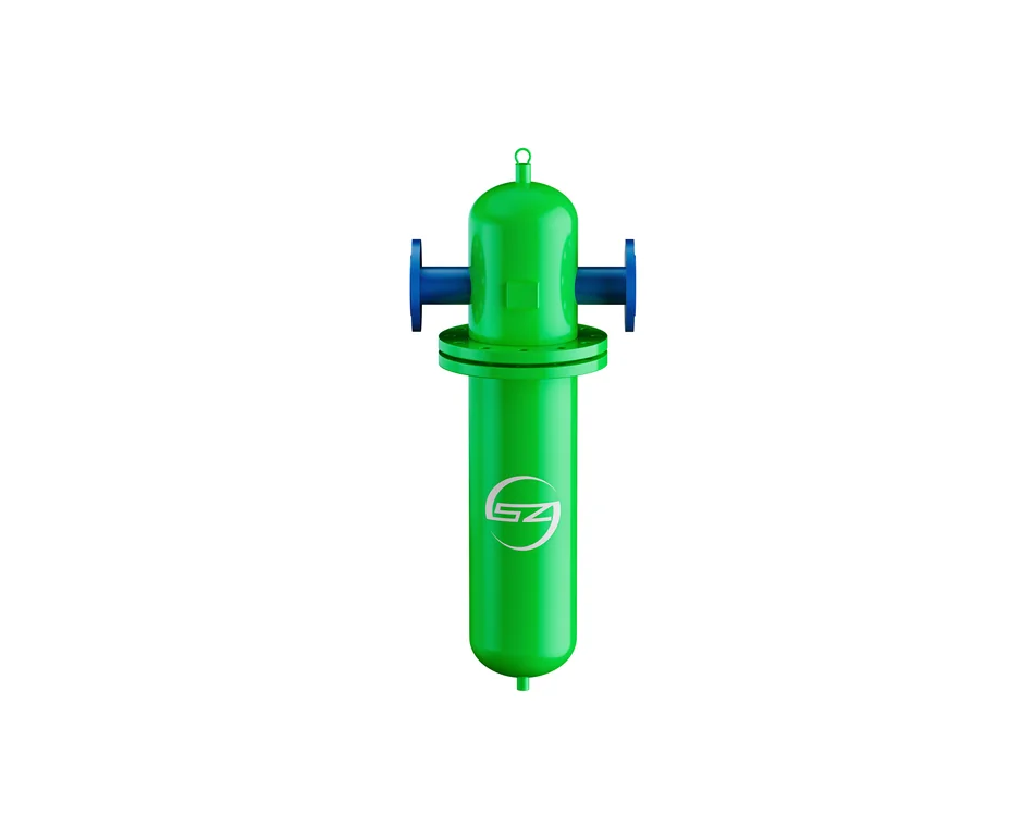
Point-of-use filtration is the final control step, and the housing in the image above is the kind of component that belongs close to the booth rather than only in the compressor room. Place coarse and fine filtration in the correct sequence, add an activated carbon stage where oil vapour is a concern, and provide isolation valves and a differential pressure indicator so elements can be changed without shutting the whole plant. Every additional stage introduces some pressure loss, so the sequence has to be reconciled with the pressure budget built in Step 1.
Oil-free generation versus downstream filtration
Two valid architectures exist. An oil-injected screw compressor followed by a properly engineered filter train can meet many finishing requirements, provided element changes are disciplined and monitored. An oil-free compressor removes the contaminant at source, which reduces the number of consumables and failure modes in the air path but changes the capital cost and the maintenance profile. Neither approach removes the need for drying: water vapour is present in the intake air regardless of how the airend is lubricated. Write the purity requirement first, then compare architectures against it. Our oil-free compressor product range shows the available technologies in one place.
Where Class 0 certification fits in the evidence
Where a specification calls for Class 0, ask for the certificate itself and read its scope. SEIZE AIR holds a Class 0 oil-free certificate for the SWT dry screw range (certificate 08823P10001, issued by GC, valid until 4 January 2028) and one for the water-lubricated range (GC24009009000223, same validity date), both referencing ISO 8573-1:2010, ISO 8573-2:2018 and ISO 8573-5:2001. The certificates list the covered models; do not extend a claim to a model outside that list. Our comparison of water-injected and dry Class 0 machines explains the practical differences between the two routes. Confirm current validity and scope against the original document before placing an order.
Step 3: Choose the compressor type and its control strategy
Once flow, pressure, duty pattern and purity are fixed, the machine family becomes a much shorter conversation. Small booths value quiet, compact, oil-free operation. Larger or multi-booth installations value part-load efficiency and the ability to hold a stable header pressure through rapid demand changes. Skid or container solutions become relevant when a complete air station has to be delivered and commissioned with minimal site work. In every case, ask for the free air delivery at your working pressure and site conditions rather than a generic brochure range.
Oil-free scroll compressors for small booths
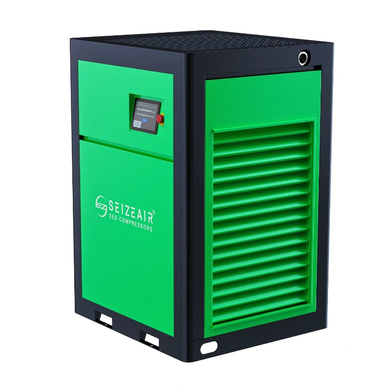
For a single-booth refinish shop, a small laboratory-like finishing cell or a low-volume furniture line, an oil-free scroll package is often the cleanest starting point. According to the parameter table on our SWO series oil-free scroll compressor page, the range spans seven models from 7.5 kW to 37 kW, with free air delivery from 0.8 to 4.0 m³/min, a maximum discharge pressure of 8 bar, and listed sound levels from 55±3 to 64±3 dB(A). Use those figures as catalogue data for the listed models and verify the current table for the exact configuration before ordering. The low noise figure matters where the machine sits near the preparation area rather than in a remote plant room.
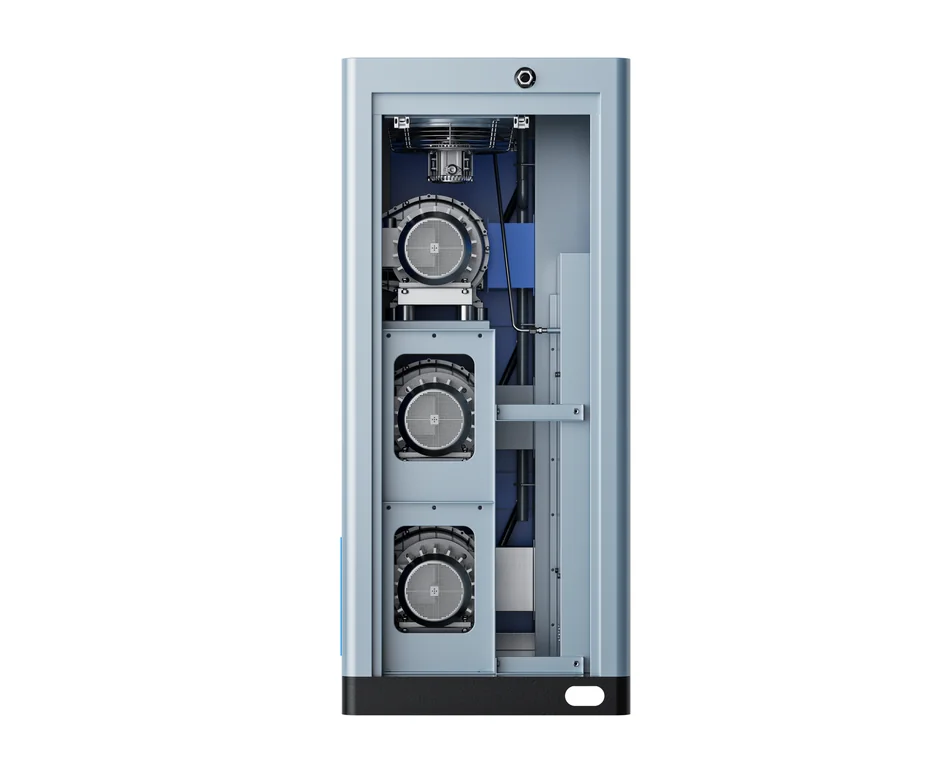
The cabinet layout also makes service access straightforward, which supports the filter and drain checks described later in this guide. Where demand exceeds what a scroll bank can reasonably cover, or where several booths share a header, a screw-based station with speed control is usually a better fit. A modular scroll bank can still be a good answer if redundancy is important: one module can be serviced while the others keep a reduced but usable supply. Ask the supplier to show the part-load behaviour of whichever arrangement is proposed, not only its full-load rating.
Variable speed rotary screw for changing demand
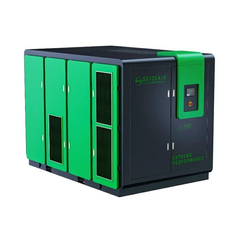
A booth where guns start and stop constantly produces a jagged demand curve. A fixed-speed machine responds by loading and unloading, which wastes energy during the unloaded period and can allow wider pressure swings at the header. A variable speed drive matches motor speed to actual air use, holding a narrower pressure band and avoiding the repeated start-stop cycle. Our permanent magnet variable speed screw compressors are designed for this pattern. As a catalogue example of the small end of that range, the SZ-15PM is listed at 11 kW with a delivery of 0.72 to 1.79 m³/min at 7.5 bar; treat it as an illustration of how a turndown range is published, not as a recommendation for your booth.
Variable speed is not a universal answer. At a steady, continuous load a well-selected fixed-speed machine can be entirely appropriate, and a multi-machine sequencing controller may serve a large plant better. The right question is how much time the system spends away from its design point. Ask for a load profile from the supplier and compare it with the shift pattern you recorded in Step 1. Include the pressure band required at the gun in the same discussion, because a narrow band is a legitimate reason to prefer speed control.
All-in-one packages for compact installations
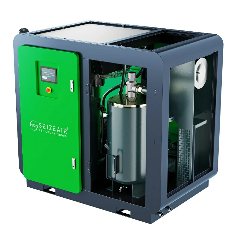
Where space is tight, an integrated package combining the compressor, dryer, receiver and filtration on one base removes a surprising amount of field piping and commissioning risk. The transparent unit shown below makes the internal arrangement visible: airend, treatment components and storage share a factory-built frame, so the air path is short and the drain points are known. Such packages suit a single booth or a small workshop, and they also simplify relocation if the finishing area moves. Check the actual treatment stages included in the specific package, because “with dryer” does not automatically mean the purity class your coating requires.
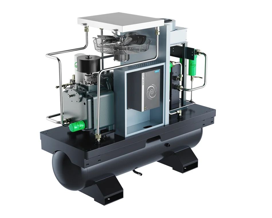
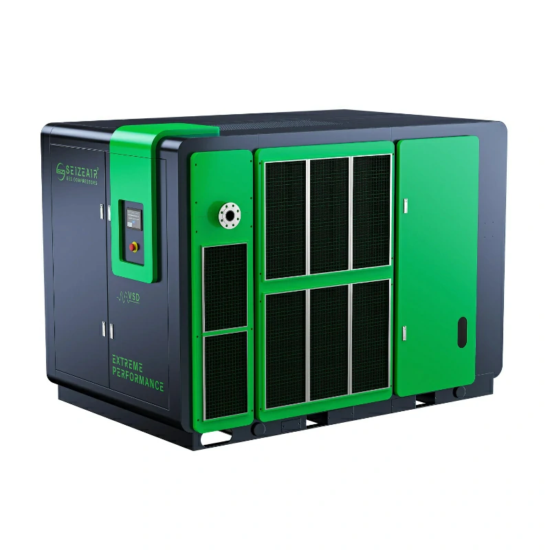
For a larger installation, the same logic applies at station level. A skid-mounted or containerised air station arrives as a tested assembly with the compressor, treatment, receiver and controls already integrated, which reduces the number of site interfaces to electricity, air and drains. If your project involves a new finishing hall, ask whether a pre-assembled station shortens the commissioning schedule enough to matter. The choice between a compact package and a full station is mostly about flow, redundancy and how many booths depend on the same header.
Step 4: Specify the drying and filtration train
Drying is sized from the required pressure dew point, the inlet temperature, the working pressure and the peak flow. A refrigerated dryer is the common choice for a booth in a conditioned space where the line temperature stays above freezing. A desiccant dryer is considered where the specified dew point is lower or where lines pass through cold areas. Correction factors for high inlet temperature or elevated ambient conditions matter, and the dryer should be rated for the peak flow of the whole station, not the average flow of one gun. Ask for the correction data used in the selection.
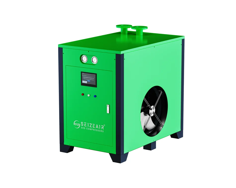
The dryer is only one element in the train. A typical arrangement places a water separator and bulk liquid removal after the receiver, a pre-filter ahead of the dryer to protect it, the dryer itself, then finer filtration and, where needed, an activated carbon stage near the point of use. Each stage needs an isolation valve, a drain and a way to verify its condition. Our refrigerated dryer range covers water-cooled and air-cooled variants; the right choice depends on the plant room’s cooling water and ventilation, not on a preference for one cabinet style.
Select the dryer from the dew point, not from a habit
Write the target pressure dew point into the specification and state where in the system it must be achieved. Then work backwards through the coldest point the air will see. If the booth is in a temperature-controlled hall but the header crosses an unheated loading bay, the bay governs. If production starts before the plant room warms up in winter, the morning condition governs. Seasonal behaviour is a common reason why a system that performs well in summer produces blushing in the colder months. Include the lowest expected line temperature in the enquiry so the dryer selection is defensible.
Where dew point is critical, specify a dew point monitor with an alarm rather than relying on a periodic visual check. A hygrometer at the point of use tells you what the gun actually receives, which is the quantity that matters. Combine that reading with differential pressure across the filters: together they separate a dryer problem from a blocked element or a failed drain. Neither instrument replaces a proper maintenance routine, but both turn an invisible failure into a logged event that can be acted on before scrap is produced.
Sequence the filters and make condensate removal reliable
Coarse filtration protects the dryer; fine filtration and carbon protect the finish. Installing them in the wrong order shortens element life and can push contamination downstream. Label each housing with its grade, element part number and change date, and keep spares on site. Condensate is the other half of the problem: automatic drains fail silently, and a float drain blocked by sludge can empty into the line instead of the waste. Fit a drain with a test button, verify it during the daily walk-through, and route the discharge to an oil-water separator where local rules require it.
Do not forget the bypass. A maintenance bypass is useful, but an open bypass valve left after a service is a direct path for wet, untreated air to reach the booth. Use a lockable or clearly flagged valve and add bypass status to the commissioning and handover checklist. Where a plant has several booths, a single shared treatment train creates a common-cause failure; consider separate point-of-use polish filters for the most sensitive finishing station so that one contaminated element does not stop the whole line.
Step 5: Size the receiver and the distribution network
A receiver does four jobs in a finishing system: it buffers short demand peaks, it lets condensate drop out before the dryer, it dampens pressure pulsation, and it gives the compressor a sane loading cycle. Sizing should consider the largest single demand event, the acceptable pressure swing at the header, and the control behaviour of the compressor. A variable speed machine and a fixed-speed machine will not necessarily want the same storage volume. Place the wet receiver before the dryer and consider a smaller dry receiver downstream where the distribution line is long.
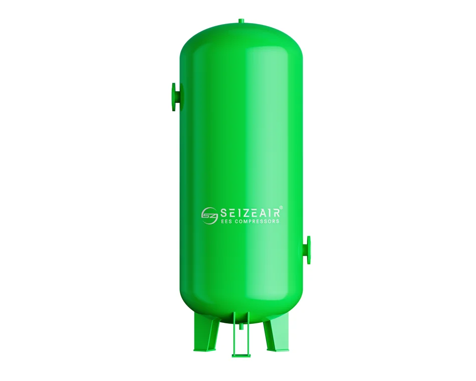
The vessel is a pressure item with its own documentation requirements. Confirm the design code, the inspection regime, the relief valve setting and the registration obligations that apply in your country before installation. Provide a drain at the lowest point, a pressure gauge, and safe access for inspection. Where several receivers are installed, label which side of the dryer each sits on; a drawing that does not show this distinction tends to be misread during future modifications, with the result that untreated air is piped straight to a booth.
Pipe sizing, hose losses and regulator placement
Distribution should be sized for the simultaneous peak flow at an acceptable velocity and pressure loss, with a ring main where multiple booths need similar pressure. Long runs, undersized quick couplers and coiled hoses are frequent sources of loss, and the flexible hose from the drop leg to the gun is often the worst offender. Use a drop leg with a water trap and a take-off from the top of the header, so condensate continues along the main instead of feeding the booth. Slope the main and provide drain points at low spots and at the end of each branch.
Regulators belong at the point of use, with a gauge readable by the operator. Setting the compressor to a higher pressure to compensate for a bad hose is a temporary fix that increases air consumption at every leak and can push the dryer outside its rated correction. Measure the pressure at the gun while spraying, then at the header, and record the difference as the installed loss. That number is a useful baseline: a gradual increase over months points to fouling, a step change points to a modification or a failing component.
Step 6: Booth safety, ventilation and compliance
Spraying flammable or combustible coatings introduces hazards that have nothing to do with compressor performance but everything to do with where the compressor and its electrical equipment are placed. Ventilation, ignition control, static bonding, overspray filtration and the classification of electrical equipment all belong in the booth design. Standards bodies such as the National Fire Protection Association publish the relevant spray application codes; consult the edition and jurisdiction that apply to your site and involve a qualified designer rather than treating an article as a compliance assessment.
Ignition sources, air intake and equipment location
The compressor should draw clean, cool air from outside the spray zone, never from an atmosphere containing solvent vapour or overspray. Intake filtration protects the airend, but it also needs a maintenance schedule; a clogged intake reduces flow and raises discharge temperature. Electrical panels, drive cabinets and hot surfaces should be located with the hazardous area classification in mind. Static bonding of the booth, the part, the hose and the air line deserves the same attention as the more obvious flash-off and ventilation requirements. Where breathing air is supplied to an operator, it is a separate regulated system and must never be drawn from the plant compressed air network.
Ventilation, PPE and housekeeping
Maintain the booth airflow specified by its designer and verify it after any filter change or duct modification. Keep the compressor room ventilated so that inlet temperature stays within the equipment’s documented range, and keep solvent storage away from the intake. Personal protective equipment, solvent handling, waste collection and cleaning procedures are governed by the coating safety data sheet and local regulation. None of these measures is a substitute for a site-specific risk assessment, and none should be inferred from a compressor catalogue. Compressed air itself is a hazard: never direct a hose at skin or clothing, and use a regulated blow-off nozzle.
A sizing worksheet you can fill in with real data
The table below deliberately contains no invented numbers. Fill every cell from the spray gun data sheet, the coating technical data sheet, a site measurement or a supplier quotation. Keeping the source in the last column makes the worksheet auditable when a second booth is added or when a defect investigation starts. If a cell cannot be filled with an evidenced value, mark it as open and resolve it before committing to a machine size.
Worksheet fields and where each value comes from
| Input | Value | Unit | Source to check |
|---|---|---|---|
| Gun air consumption at stated inlet pressure | ________ | m³/min or cfm | Spray gun data sheet, nozzle and cap set |
| Required pressure at the gun inlet | ________ | bar or psi | Gun and coating documentation |
| Maximum guns operating simultaneously | ________ | count | Shift observation with production supervisor |
| Other simultaneous pneumatic users | ________ | m³/min or cfm | Plant equipment list and site survey |
| Installed pressure loss to the farthest gun | ________ | bar or psi | Measured gauge difference while spraying |
| Target air purity class or explicit limits | ________ | ISO 8573-1 class | Coating technical data sheet |
| Target pressure dew point and its location | ________ | °C | Coating specification and coldest line point |
| Lowest expected air line temperature | ________ | °C | Site survey across seasons |
| Compressor free air delivery at working pressure | ________ | m³/min | Quoted catalogue table with reference conditions |
| Receiver volume and relief valve setting | ________ | litres / bar | Vessel documentation and local rules |
Once the worksheet is complete, add the flows, convert every value to one consistent unit, and compare the total with the compressor’s free air delivery at your working pressure and site conditions. Then compare the required gun pressure plus installed losses with the pressure the station can hold at peak flow. Only after both checks pass should the dryer, filters, receiver and pipework be finalised. Re-run the worksheet whenever a gun, nozzle, coating or booth layout changes; the calculation is cheap, while a retrofit after defects appear is not.
Installation and commissioning checklist
A clean specification can still be undone by a rushed installation. Use the following sequence at handover, and keep signed records with the plant documentation. Each item is phrased as a verification question so it can be ticked only when someone has actually observed the result rather than assumed it from a drawing.
Handover checks to tick off on site
- Is the compressor intake located outside the spray zone, with clean, cool air and an accessible filter?
- Does the plant room ventilation keep intake temperature inside the equipment’s documented range?
- Is the wet receiver installed before the dryer, with a working drain at its lowest point?
- Are dryer, pre-filter, fine filter and carbon stage installed in the specified sequence and labelled?
- Have all automatic drains been operated manually with the test button and observed discharging correctly?
- Is every bypass valve closed, locked or flagged, and is its status recorded on the handover sheet?
- Does each drop leg take air from the top of the header and include a water trap?
- Has the main been sloped, with drain points at low spots and at the end of branches?
- Was pressure measured at the gun while spraying, and does it meet the coating requirement?
- Was the pressure drop across each filter recorded as a clean baseline?
- Has the dew point at the point of use been measured against the specified target?
- Was a test panel sprayed and inspected under the booth’s normal lighting before sign-off?
- Are the vessel documents, relief valve certificate and electrical classification records filed?
- Have operators been trained to check drains, gauges and filter indicators at the start of a shift?
Commissioning is also the moment to write down the numbers that make future troubleshooting possible: clean filter differential pressures, header pressure at peak flow, dew point reading, dryer inlet temperature and the pressure at the farthest gun. Without that baseline, a later reading has no context and every investigation starts from scratch. A single page of commissioning data is usually worth more than a folder of brochures when a finishing defect appears six months later.
Maintenance that protects the finish
Finishing air systems fail gradually. A drain sticks, an element loads up, a dew point probe drifts, and the first sign is a slow rise in rework rather than an alarm. A short, repeatable routine tied to the booth’s production rhythm is more effective than an ambitious schedule nobody follows. Assign each task to a named role, and record exceptions with the date, the booth and the observed reading.
A routine grouped by interval
- Every shift: check the receiver and filter drains, note header and gun pressure, and look for water in the drop leg trap.
- Every shift: confirm the dew point or dryer status indication and check that no bypass valve has been left open.
- Weekly: inspect intake filters, listen for unusual compressor noise, and check for leaks with an appropriate method while the line is live.
- Monthly: record differential pressure across each filter housing and compare it with the commissioning baseline.
- Monthly: verify the automatic drains by operating the test function and observing discharge to the separator.
- At the interval stated by the manufacturer: replace filter elements, service the dryer and change compressor consumables with genuine parts.
- At the interval required locally: inspect the receiver, test the relief valve and review the vessel documentation.
- After any modification: repeat the point-of-use pressure and dew point checks before releasing the booth back to production.
Two habits make the routine pay off. First, treat a change in differential pressure as information: a slow rise means an element is loading, while a sudden drop can mean a damaged element or a bypass. Second, keep the waste path clean. A separator that is never emptied eventually pushes condensate back into places it should never reach. Neither task is technically demanding, but both are easy to omit when production is busy, which is exactly when a contaminated panel is most likely to be missed.
Troubleshooting: trace the defect back to the air
Use the table as a starting hypothesis, not a verdict. Confirm each suspected cause with a measurement before changing parts. Several defects share the same visible symptom, and replacing a compressor when the real problem is a blocked drain is an expensive way to learn that lesson. Where two booths share a header, compare their results: a defect confined to one booth usually points to that branch, while a plant-wide change points to generation or central treatment.
| Observed symptom | Likely air-side cause | Check to confirm |
|---|---|---|
| Fisheyes or craters | Oil aerosol or vapour reaching the gun | Carbon filter condition, coalescing element, oil carry-over evidence |
| Milky or cloudy film | Liquid water or excessive humidity | Dew point at point of use, drains, cold sections of the header |
| Spatter or irregular atomisation | Pressure fluctuation at the gun inlet | Gun gauge while spraying, receiver behaviour, simultaneous demand |
| Dirt nibs and roughness | Particles from pipe scale, desiccant dust or filters | Point-of-use filter, internal pipe condition, element seating |
| Poor intercoat adhesion | Oil or silicone-type contamination in the air path | Audit of all filters, cleaning products used near the intake |
| Defects appear only in cold weather | Condensation in unheated line sections | Lowest line temperature, dew point target, insulation and drains |
| Defects appear after maintenance | Open bypass, wrong element grade or reversed filter order | Valve status, housing labels, service record |
If the checks point upstream of the treatment train, resist the temptation to raise the compressor pressure. That change masks a flow restriction for a while, increases leakage losses everywhere on the network, and may push a dryer beyond its rated correction. Fix the restriction, the drain or the element instead, then repeat the point-of-use measurements. Document the root cause and the corrective action so the next occurrence is diagnosed in minutes rather than days.
Buying checklist: what to ask a supplier
A well-prepared enquiry produces a comparable quotation and exposes assumptions early. Ask for the following in writing, and expect the supplier to ask you for the worksheet from Step 1 in return. A quote that answers all of these points is far easier to evaluate than a single line with a kilowatt rating and a price.
Questions to put in the enquiry
- What free air delivery is guaranteed at our working pressure and declared site conditions, and under which test standard?
- Which pressure band can the control system hold at the header during the simultaneous peak we described?
- Which air purity class does the complete train meet, and where in the system is that verified?
- What pressure dew point is guaranteed, at which flow, inlet temperature and ambient condition?
- Which filter grades are included, in what order, and what is the clean and change-out differential pressure?
- What is the total pressure loss from the compressor outlet to the gun at peak flow?
- Is a receiver included, on which side of the dryer, and what documentation comes with the vessel?
- How are condensate drains arranged, tested and routed to an oil-water separator where required?
- What is the recommended spare parts list and service interval for the specific configuration quoted?
- Which certificates apply to the quoted models, and can their scope and validity be checked against the originals?
- What commissioning measurements and test panel acceptance will be performed at handover?
- Who is responsible for booth ventilation, hazardous area classification and local compliance?
Also ask how the system will be supported after installation. A finishing line cannot wait weeks for a filter element or a drain solenoid, and a supplier who understands the application will propose a sensible spares kit with the quotation. Where a booth is part of a larger plant, clarify who owns the shared header and how a future extension will be evaluated; adding a second spray line is much cheaper if the original design recorded its pressure and flow reserves.
Frequently asked questions
What size air compressor for spray painting do I need?
Size it from the spray gun data sheet rather than from a rule of thumb. Add the consumption of every gun that can be triggered at the same time, add other simultaneous pneumatic users, then compare the total with the free air delivery quoted at your working pressure and reference conditions. Confirm the result with a gauge at the gun while spraying. If you cannot obtain a reliable consumption figure for a nozzle set, measure it with a flow meter during a trial instead of guessing. Our auto body shop compressor guide discusses the small-workshop case separately.
Do I need an oil-free compressor for spray painting?
Not always. An oil-injected machine with a correctly engineered and maintained filter train can meet many finishing specifications. Oil-free generation removes the contaminant at source and reduces the number of consumables in the air path, which lowers a class of maintenance risk. The decision should follow the purity class in the coating documentation and your cost of rework. Either architecture still needs proper drying, because water vapour enters with the intake air regardless of the compression technology.
Which air dryer is right for a paint booth?
Choose from the required pressure dew point and the coldest temperature the air line will see, then size for peak flow with the appropriate correction factors for inlet and ambient temperature. A refrigerated dryer suits many conditioned indoor installations; a desiccant dryer is considered for lower dew point requirements or cold line sections. Whichever type is chosen, pair it with reliable condensate drains and a dew point indication at the point of use so performance is observable rather than assumed.
Why does my finish look good in the morning but fail later?
Look for a load- or temperature-related pattern. Later shifts may have more guns in use, warmer plant room air, a receiver drain that has filled during the day, or a dryer that is approaching its correction limit. Compare header pressure and dew point readings at both times and check whether the difference coincides with a second operator starting work. A log that records time, booth, reading and defect type usually reveals the correlation faster than replacing components at random.
Can I use the same compressor for the booth and the rest of the shop?
Yes, provided the demand profile includes every simultaneous user and the treatment train is sized for the whole flow. Point-of-use polish filtration near the booth is still advisable, because it isolates the most sensitive application from upstream upsets. Be especially careful with blow-off stations and pneumatic tools that can create sudden pressure dips while a panel is being sprayed. Where the shop’s demand is highly variable, a dedicated small unit for the booth may deliver a more stable finish than one large shared machine.
Does a bigger receiver tank improve the paint finish?
Storage helps damp short peaks and gives condensate a place to drop out, but it cannot correct an undersized compressor, a high pressure loss in the hose or an inadequate dryer. If the header pressure sags during a long spray pass, more volume only delays the sag. Diagnose the shape of the demand and the condition of the distribution first, then size storage to suit the compressor’s control behaviour. A receiver is one element of a designed system, not a substitute for one.
How often should the booth air filters be changed?
Follow the element manufacturer’s interval, but let differential pressure decide the actual date. Record the clean pressure drop at commissioning, check it at a fixed interval, and replace the element when it reaches the stated change-out value or sooner if a rising trend appears. A calendar-only schedule can waste usable elements or, worse, miss an early blockage caused by an upstream fault. Keep spare elements and their part numbers with the maintenance record.
Bringing the system together
An air compressor for spray painting earns its keep when flow, pressure and purity are all verified at the gun, not just at the compressor outlet. Build the demand profile from real equipment data, write the air purity class and dew point into the specification, choose a compressor whose control strategy matches the shift pattern, and treat drying, filtration, storage and distribution as parts of one system. Commission it with recorded baseline readings, then keep it honest with a short maintenance routine and a defect log. That discipline turns a finish problem from a recurring mystery into a measurement with an obvious next step.
If you are planning a new booth or upgrading an existing finishing line, share your spray gun data sheets, the number of simultaneous operators, the coating’s air purity requirement and the layout of your distribution line. Contact the SEIZE AIR team to review the worksheet and discuss a compressor, treatment train and station layout built around those inputs. We will respond with the catalogue data and documentation relevant to the specific models under consideration, so you can compare options against evidence rather than assumptions.